
Manual
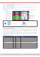
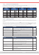
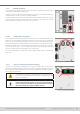
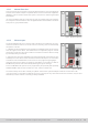
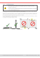
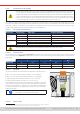
Table Of Contents
- 1. General
- 1.1 About this document
- 1.2 Warranty
- 1.3 Limitation of liability
- 1.4 Disposal of equipment
- 1.5 Product key
- 1.6 Intended usage
- 1.7 Safety
- 1.8 Technical Data
- 1.9 Construction and function
- 1.9.1 General description
- 1.9.2 Block diagram
- 1.9.3 Scope of delivery
- 1.9.4 Accessories
- 1.9.5 Options
- 1.9.6 The control panel (HMI)
- 1.9.7 USB port (rear side)
- 1.9.8 Interface module slot
- 1.9.9 Analog interface
- 1.9.10 “Share BUS” connector
- 1.9.11 “Sense” connector (remote sensing)
- 1.9.12 Master-Slave bus
- 1.9.13 Ethernet port
- 2. Installation & commissioning
- 2.1 Transport and storage
- 2.2 Unpacking and visual check
- 2.3 Installation
- 2.3.1 Safety procedures before installation and use
- 2.3.2 Preparation
- 2.3.3 Installing the device
- 2.3.4 Connection to AC supply
- 2.3.5 Connection to DC sources
- 2.3.6 Connection of remote sensing
- 2.3.7 Grounding of the DC terminal
- 2.3.8 Installation of an interface module
- 2.3.9 Connection of the analog interface
- 2.3.10 Connection of the Share bus
- 2.3.11 Connection of the USB port (rear side)
- 2.3.12 Initial commission
- 2.3.13 Commission after a firmware update or a long period of non-use
- 3. Operation and application
- 3.1 Important notes
- 3.2 Operating modes
- 3.3 Alarm conditions
- 3.4 Manual operation
- 3.5 Remote control
- 3.6 Alarms and monitoring
- 3.7 Locking the control panel (HMI)
- 3.8 Locking the adjustment limits and user profiles
- 3.9 Loading and saving user profiles
- 3.10 The function generator
- 3.10.1 Introduction
- 3.10.2 General
- 3.10.3 Method of operation
- 3.10.4 Manual operation
- 3.10.5 Sine wave function
- 3.10.6 Triangular function
- 3.10.7 Rectangular function
- 3.10.8 Trapezoidal function
- 3.10.9 DIN 40839 function
- 3.10.10 Arbitrary function
- 3.10.11 Ramp function
- 3.10.12 IU table function (XY table)
- 3.10.13 Battery test function
- 3.10.14 MPP tracking function
- 3.10.15 Remote control of the function generator
- 3.11 Other applications
- 4. Service and maintenance
- 5. Contact and support

© EA Elektro-Automatik in 2022, this information is subject to change without notice 2333200840_manual_elr_10000_2u_3kw_en_02
1.9.6.4 Resolution of the displayed values
In the display, set values can be adjusted in xed increments. The number of decimal places depends on the device model.
The values have 4 or 5 digits. Actual and set values always have the same number of digits.
Adjustment resolution and number of digits of set values in the display:
Voltage,
OVP, UVD, OVD,
U-min, U-max
Current,
OCP, UCD, OCD,
I-min, I-max
Power,
OPP, OPD,
P-max
Resistance,
R-max
Nominal
Digits
Min.,
incre-
ment
Nominal*
Digits
Min.,
incre-
ment
Nominal*
Digits
Min.,
incre-
ment
Nominal
Digits
Min., in-
crement
80 V 4 0.01 V <10 A 4 0.001 A 1500 W 4 1 W <10 Ω 5 0.0001 Ω
200 V 5 0.01 V ≥10...<30 A 5 0.001 A 3000 W 4 1 W ≥10 Ω ... <100 Ω 5 0.001 Ω
360 V 4 0.1 V ≥30...<100 A 4 0.01 A MS <100 kW 4 0.01 kW ≥100 Ω ... <1000 Ω 5 0.01 Ω
500 V 4 0.1 V >100 A 4 0.1 A MS >100 kW 4 0.1 kW >1000 Ω 5 0.1 Ω
750 V 4 0.1 V MS ≥1000 A 4 1 A
≥1000 V 5 0.1 V
* MS = Master-slave
1.9.6.5 USB port (front side)
The frontal USB port, located above the rotary knobs, is intended for the connection of standard USB sticks and can be used
for loading or saving sequences for the arbitrary and the XY generator, as well as for recording measured data during running
operation.
USB 2.0 and 3.0 sticks are well supported. The stick must be FAT32 formatted. All supported les must be held in a desig-
nated folder in the root path of the USB stick in order to be found. This folder must be named HMI_FILES, such that a PC
would recognize the path G:\HMI_FILES if the drive were to be assigned the letter G. Subfolders are supported. In case there
are multiple les of the same type, e. g. such starting with “wave”, the device will list the 20 rst it can nd.
The control panel of the device can read the following le types and names from a stick:
File name Description Section
wave_u<arbitrary_text>.csv
wave_i<arbitrary_text>.csv
Function generator for an arbitrary function on voltage (U) or current (I)
The name must begin with
wave_u / wave_i
, the rest is user dened.
3.10.10.1
prole_<arbitrary_text>.csv Previously saved user prole. A max. of 10 les to select from is shown
when loading a user prole.
3.9
mpp_curve_<arbitrary_text>.csv User-dened curve data (100 voltage values) for mode MPP4 of the
MPPT function
3.10.14.5
iu<arbitrary_text>.csv IU table for the XY function generator.
The name must begin with
iu
, the rest can be user dened.
3.10.12
The control panel of the device can save the following le types and names to a USB stick:
File name Description Section
usb_log_<nr>.csv File with log data recorded during normal operation in all modes. The le
layout is identical to the those generated from the Logging feature in EA
Power Control. The <nr> eld in the le name is automatically counted
up if equally named les already exist in the folder.
3.4.8
prole_<nr>.csv Saved user prole. The number in the le name is a counter and not
related to the actual user prole number in the HMI. A max. of 10 les to
select from is shown when loading a user prole.
3.9
wave_u<nr>.csv
wave_i<nr>.csv
Sequence point data (here: sequences) of either voltage U or current I
from arbitrary function generator
3.10.10.1
battery_test_log_<nr>.csv File with log data recorded from the battery test function. For a battery
test log, data different and/or additional to log data of normal USB log-
ging is recorded.
3.10.13.5
mpp_result_<nr>.csv Result data from MPP tracking mode 4 in form of a table with 100 data
groups (Umpp, Impp, Pmpp)
3.10.14.6