
Manual
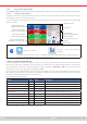
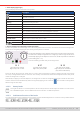
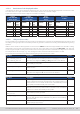
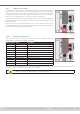
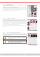
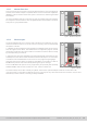
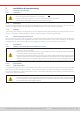
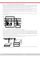
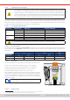
Table Of Contents
- 1. General
- 1.1 About this document
- 1.2 Warranty
- 1.3 Limitation of liability
- 1.4 Disposal of equipment
- 1.5 Product key
- 1.6 Intended usage
- 1.7 Safety
- 1.8 Technical Data
- 1.9 Construction and function
- 1.9.1 General description
- 1.9.2 Block diagram
- 1.9.3 Scope of delivery
- 1.9.4 Accessories
- 1.9.5 Options
- 1.9.6 The control panel (HMI)
- 1.9.7 USB port (rear side)
- 1.9.8 Interface module slot
- 1.9.9 Analog interface
- 1.9.10 “Share BUS” connector
- 1.9.11 “Sense” connector (remote sensing)
- 1.9.12 Master-Slave bus
- 1.9.13 Ethernet port
- 2. Installation & commissioning
- 2.1 Transport and storage
- 2.2 Unpacking and visual check
- 2.3 Installation
- 2.3.1 Safety procedures before installation and use
- 2.3.2 Preparation
- 2.3.3 Installing the device
- 2.3.4 Connection to AC supply
- 2.3.5 Connection to DC sources
- 2.3.6 Connection of remote sensing
- 2.3.7 Grounding of the DC terminal
- 2.3.8 Installation of an interface module
- 2.3.9 Connection of the analog interface
- 2.3.10 Connection of the Share bus
- 2.3.11 Connection of the USB port (rear side)
- 2.3.12 Initial commission
- 2.3.13 Commission after a firmware update or a long period of non-use
- 3. Operation and application
- 3.1 Important notes
- 3.2 Operating modes
- 3.3 Alarm conditions
- 3.4 Manual operation
- 3.5 Remote control
- 3.6 Alarms and monitoring
- 3.7 Locking the control panel (HMI)
- 3.8 Locking the adjustment limits and user profiles
- 3.9 Loading and saving user profiles
- 3.10 The function generator
- 3.10.1 Introduction
- 3.10.2 General
- 3.10.3 Method of operation
- 3.10.4 Manual operation
- 3.10.5 Sine wave function
- 3.10.6 Triangular function
- 3.10.7 Rectangular function
- 3.10.8 Trapezoidal function
- 3.10.9 DIN 40839 function
- 3.10.10 Arbitrary function
- 3.10.11 Ramp function
- 3.10.12 IU table function (XY table)
- 3.10.13 Battery test function
- 3.10.14 MPP tracking function
- 3.10.15 Remote control of the function generator
- 3.11 Other applications
- 4. Service and maintenance
- 5. Contact and support

© EA Elektro-Automatik in 2022, this information is subject to change without notice 2233200840_manual_elr_10000_2u_3kw_en_02
• Status display (upper right)
This area displays various status texts and symbols:
Display Description
The HMI is locked
The HMI is unlocked
Remote: The device is under remote control from....
Analog ...the built-in analog interface
ETH ...the built-in Ethernet interface
USB & others ...the built-in USB port or a plug in interface module
Local The device has been locked by the user explicitly against remote control
Alarm: Alarm condition which has not been acknowledged or still exists.
Event: A user dened event has occurred which is not yet acknowledged.
MS mode: Master (n Sl) Master-slave mode activated, device is master of n slaves
MS mode: Slave Master-slave mode activated, device is slave
FG: Function generator activated, function loaded (only in remote control)
/
Data logging to USB stick active or failed
• Area for assigning the rotary knobs and DC input status
The two rotary knobs next to the display screen can be assigned to various functions. This area shows the actual assignments.
These can be changed by tapping this area, as long as the panel is not locked.
The physical quantities on the depiction of the knob show the current assignment.
The left knob is always assigned to the voltage (U), while the right knob can be
switched by tapping on the depiction. Furthermore, the DC input status is indicated
by two LEDs (green = on).
There are following possible rotary know assignments:
U I U P U R
Left rotary knob: voltage
Right rotary knob: current
Left rotary knob: voltage
Right rotary knob: power
Left rotary knob: voltage
Right rotary knob: resistance
(only with R mode active)
Due to the device having two set values each for current, power and resistance, tapping multiple times will cycle through
the 4 resp. 6 assignable set values for this knob. The currently not selected set values can’t be adjusted via the rotary knob,
unless the assignment is changed.
Alternatively to tapping on the knob depiction, the assignment can also be changed by tapping the colored set value areas.
However, values can be entered directly with a ten-key pad by tapping on the small icon . This method of entering values
allows for big set value steps.
1.9.6.2 Rotary knobs
As long as the device is in manual operation, the two rotary knobs are used to adjust set values in the main screen.
For a detailed description of the individual functions see section
“3.4. Manual operation”.
1.9.6.3 Pushbutton function of the knobs
The rotary knobs also have a pushbutton function which is used in all value adjustment to move the cursor by rotation like this: