
Manual
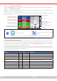
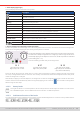
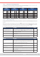
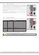
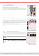
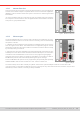
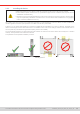
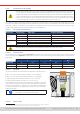
Table Of Contents
- 1. General
- 1.1 About this document
- 1.2 Warranty
- 1.3 Limitation of liability
- 1.4 Disposal of equipment
- 1.5 Product key
- 1.6 Intended usage
- 1.7 Safety
- 1.8 Technical Data
- 1.9 Construction and function
- 1.9.1 General description
- 1.9.2 Block diagram
- 1.9.3 Scope of delivery
- 1.9.4 Accessories
- 1.9.5 Options
- 1.9.6 The control panel (HMI)
- 1.9.7 USB port (rear side)
- 1.9.8 Interface module slot
- 1.9.9 Analog interface
- 1.9.10 “Share BUS” connector
- 1.9.11 “Sense” connector (remote sensing)
- 1.9.12 Master-Slave bus
- 1.9.13 Ethernet port
- 2. Installation & commissioning
- 2.1 Transport and storage
- 2.2 Unpacking and visual check
- 2.3 Installation
- 2.3.1 Safety procedures before installation and use
- 2.3.2 Preparation
- 2.3.3 Installing the device
- 2.3.4 Connection to AC supply
- 2.3.5 Connection to DC sources
- 2.3.6 Connection of remote sensing
- 2.3.7 Grounding of the DC terminal
- 2.3.8 Installation of an interface module
- 2.3.9 Connection of the analog interface
- 2.3.10 Connection of the Share bus
- 2.3.11 Connection of the USB port (rear side)
- 2.3.12 Initial commission
- 2.3.13 Commission after a firmware update or a long period of non-use
- 3. Operation and application
- 3.1 Important notes
- 3.2 Operating modes
- 3.3 Alarm conditions
- 3.4 Manual operation
- 3.5 Remote control
- 3.6 Alarms and monitoring
- 3.7 Locking the control panel (HMI)
- 3.8 Locking the adjustment limits and user profiles
- 3.9 Loading and saving user profiles
- 3.10 The function generator
- 3.10.1 Introduction
- 3.10.2 General
- 3.10.3 Method of operation
- 3.10.4 Manual operation
- 3.10.5 Sine wave function
- 3.10.6 Triangular function
- 3.10.7 Rectangular function
- 3.10.8 Trapezoidal function
- 3.10.9 DIN 40839 function
- 3.10.10 Arbitrary function
- 3.10.11 Ramp function
- 3.10.12 IU table function (XY table)
- 3.10.13 Battery test function
- 3.10.14 MPP tracking function
- 3.10.15 Remote control of the function generator
- 3.11 Other applications
- 4. Service and maintenance
- 5. Contact and support

© EA Elektro-Automatik in 2022, this information is subject to change without notice 2133200840_manual_elr_10000_2u_3kw_en_02
1.9.6 The control panel (HMI)
The HMI (Human Machine Interface) consists of a display with touchscreen, two rotary knobs, a pushbutton and a USB port.
1.9.6.1 Touchscreen display
The graphic touchscreen display is divided into a number of areas. The complete display is touch sensitive and can be oper-
ated by nger or stylus to control the equipment.
In normal operation the left hand side is used to show actual values and set values and the right hand side is used to display
status information:
Actual voltage display
Voltage set value input
Additional status
Status area
Actual current display
Current set value input
Touch area for
rotary knob assignment
DC input status
Actual power display
Power set value input
Actual resistance display
Resistance set value input
Touch areas for menu
access
Quick menu
Touch areas may be enabled or disabled:
Black text = Enabled
Grey text = Touch area temporarily
disabled
This applies to all touch areas. Some can additionally show a small padlock sign, indicating that the fea-
ture is permanently locked, usually due to a specic setting.
• Actual / set values area (left hand side)
In normal operation the actual values (large numbers) and set values (small numbers) for voltage, current, power and re-
sistance on the DC input are displayed. The actual and set of resistance are only displayed while resistance mode is active.
When the DC input is switched on the actual regulation mode is displayed as CV, CC, CP or CR, next to the corresponding
actual value, as shown in the gure above exemplary with CC.
The set values can be adjusted with the rotary knobs next to the display screen or can be entered directly via the touchscreen.
When adjusting with the knobs, pushing the knob will select the digit to be changed. Logically, the values are increased by
clockwise turning and decreased by anti-clockwise turning.
General display and setting ranges:
Display Unit Range Description
Actual voltage V 0.2-125% U
Nom
Actual value of the voltage on the DC input
Set value of voltage V 0-102% U
Nom
Set value for limiting the DC voltage
Actual current A 0.2-125% I
Nom
Actual value of the current on the DC input
Set values of current A 0-102% I
Nom
Set value for limiting the DC current
Actual power W, kW 0.2-125% P
Nom
Actual value of power according to P = U * I
Set values of power W, kW 0-102% P
Nom
Set value for limiting DC power
Actual resistance Ω x
(1
-99999 / ∞ Actual value of the internal resistance
Set value of resistance Ω x
(1
-102% R
Max
Set value for the internal resistance
Adjustment limits ditto 0-102% nom U-max, I-min etc., related to the physical quantities
Protection settings ditto 0-110% nom OVP, OCP, OPP (related to U, I and P)
(1
Lower limit for resistance set value varies. See tables in section
1.8.3