
Manual
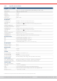
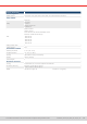
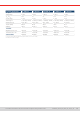
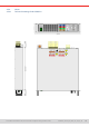
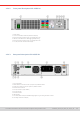
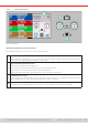
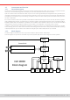
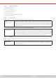
Table Of Contents
- 1. General
- 1.1 About this document
- 1.2 Warranty
- 1.3 Limitation of liability
- 1.4 Disposal of equipment
- 1.5 Product key
- 1.6 Intended usage
- 1.7 Safety
- 1.8 Technical Data
- 1.9 Construction and function
- 1.9.1 General description
- 1.9.2 Block diagram
- 1.9.3 Scope of delivery
- 1.9.4 Accessories
- 1.9.5 Options
- 1.9.6 The control panel (HMI)
- 1.9.7 USB port (rear side)
- 1.9.8 Interface module slot
- 1.9.9 Analog interface
- 1.9.10 “Share BUS” connector
- 1.9.11 “Sense” connector (remote sensing)
- 1.9.12 Master-Slave bus
- 1.9.13 Ethernet port
- 2. Installation & commissioning
- 2.1 Transport and storage
- 2.2 Unpacking and visual check
- 2.3 Installation
- 2.3.1 Safety procedures before installation and use
- 2.3.2 Preparation
- 2.3.3 Installing the device
- 2.3.4 Connection to AC supply
- 2.3.5 Connection to DC sources
- 2.3.6 Connection of remote sensing
- 2.3.7 Grounding of the DC terminal
- 2.3.8 Installation of an interface module
- 2.3.9 Connection of the analog interface
- 2.3.10 Connection of the Share bus
- 2.3.11 Connection of the USB port (rear side)
- 2.3.12 Initial commission
- 2.3.13 Commission after a firmware update or a long period of non-use
- 3. Operation and application
- 3.1 Important notes
- 3.2 Operating modes
- 3.3 Alarm conditions
- 3.4 Manual operation
- 3.5 Remote control
- 3.6 Alarms and monitoring
- 3.7 Locking the control panel (HMI)
- 3.8 Locking the adjustment limits and user profiles
- 3.9 Loading and saving user profiles
- 3.10 The function generator
- 3.10.1 Introduction
- 3.10.2 General
- 3.10.3 Method of operation
- 3.10.4 Manual operation
- 3.10.5 Sine wave function
- 3.10.6 Triangular function
- 3.10.7 Rectangular function
- 3.10.8 Trapezoidal function
- 3.10.9 DIN 40839 function
- 3.10.10 Arbitrary function
- 3.10.11 Ramp function
- 3.10.12 IU table function (XY table)
- 3.10.13 Battery test function
- 3.10.14 MPP tracking function
- 3.10.15 Remote control of the function generator
- 3.11 Other applications
- 4. Service and maintenance
- 5. Contact and support

© EA Elektro-Automatik in 2022, this information is subject to change without notice 2033200840_manual_elr_10000_2u_3kw_en_02
1.9.3 Scope of delivery
1 x Electronic load device
2 x Remote sensing plugs
1 x 1.8 m (5.9 ft) USB cable
1 x Set of DC terminal covers
1 x Sense terminal cover
1 x USB stick with documentation and software
1 x Cable tie for strain relief
1.9.4 Accessories
For all models in this series the following hardware accessories are available:
IF-AB
Interface modules
Pluggable and retrottable, digital interface modules for RS232, CANopen, Probus, ProNet,
ModBus TCP, EtherCAT or CAN are available. Details about the interface modules and the pro-
gramming of the device using those interfaces can be found in separate documentation. It’s
usually available on the USB stick, which is included with the device, or as PDF download on the
manufacturers website.
For all models in this series the following software accessories are available:
LICENSE
Software licenses
All devices of this series are shipped with a free remote control software for Windows, called EA
Power Control. Besides free-to-use apps this software has other apps like Multi Control, the Graph
and the Function Generator, which can be unlocked with a purchasable license code. These three
apps are combined under the license “Multi Control”. One license per PC required. There is a single
license and a 5-pack available, also a 14-day trial license which can be obtained upon request.
More information is available in the user manual of this software or on our website.
1.9.5 Options
These options are usually ordered along with the device, as they are permanently built in or precongured during the manu-
facturing process.
POWER RACKS
19“ rack
Racks in various congurations up to 42U as parallel systems are available, or mixed with elec-
tronic load devices to create test systems. Further information in our product catalogue, on our
website or upon request