
Manual
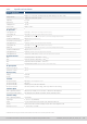
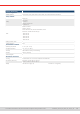
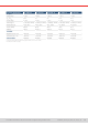
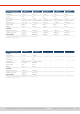
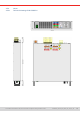
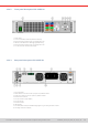
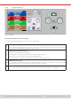
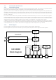
Table Of Contents
- 1. General
- 1.1 About this document
- 1.2 Warranty
- 1.3 Limitation of liability
- 1.4 Disposal of equipment
- 1.5 Product key
- 1.6 Intended usage
- 1.7 Safety
- 1.8 Technical Data
- 1.9 Construction and function
- 1.9.1 General description
- 1.9.2 Block diagram
- 1.9.3 Scope of delivery
- 1.9.4 Accessories
- 1.9.5 Options
- 1.9.6 The control panel (HMI)
- 1.9.7 USB port (rear side)
- 1.9.8 Interface module slot
- 1.9.9 Analog interface
- 1.9.10 “Share BUS” connector
- 1.9.11 “Sense” connector (remote sensing)
- 1.9.12 Master-Slave bus
- 1.9.13 Ethernet port
- 2. Installation & commissioning
- 2.1 Transport and storage
- 2.2 Unpacking and visual check
- 2.3 Installation
- 2.3.1 Safety procedures before installation and use
- 2.3.2 Preparation
- 2.3.3 Installing the device
- 2.3.4 Connection to AC supply
- 2.3.5 Connection to DC sources
- 2.3.6 Connection of remote sensing
- 2.3.7 Grounding of the DC terminal
- 2.3.8 Installation of an interface module
- 2.3.9 Connection of the analog interface
- 2.3.10 Connection of the Share bus
- 2.3.11 Connection of the USB port (rear side)
- 2.3.12 Initial commission
- 2.3.13 Commission after a firmware update or a long period of non-use
- 3. Operation and application
- 3.1 Important notes
- 3.2 Operating modes
- 3.3 Alarm conditions
- 3.4 Manual operation
- 3.5 Remote control
- 3.6 Alarms and monitoring
- 3.7 Locking the control panel (HMI)
- 3.8 Locking the adjustment limits and user profiles
- 3.9 Loading and saving user profiles
- 3.10 The function generator
- 3.10.1 Introduction
- 3.10.2 General
- 3.10.3 Method of operation
- 3.10.4 Manual operation
- 3.10.5 Sine wave function
- 3.10.6 Triangular function
- 3.10.7 Rectangular function
- 3.10.8 Trapezoidal function
- 3.10.9 DIN 40839 function
- 3.10.10 Arbitrary function
- 3.10.11 Ramp function
- 3.10.12 IU table function (XY table)
- 3.10.13 Battery test function
- 3.10.14 MPP tracking function
- 3.10.15 Remote control of the function generator
- 3.11 Other applications
- 4. Service and maintenance
- 5. Contact and support

© EA Elektro-Automatik in 2022, this information is subject to change without notice 1933200840_manual_elr_10000_2u_3kw_en_02
1.9 Construction and function
1.9 .1 General description
The devices of series ELR 10000 2U are energy recovering, switching electronic loads. The recovery or recuperation feature
inverts the consumed DC energy with an eciency of up to 95% and feeds it back into the local mains.
Apart from basic functions of electronic loads, set point curves can be generated by the integrated function generator (sine,
rectangular, triangular and other curve types). Arbitrary generator curves (up to 99 points) can be saved to and loaded from
an USB stick. For industrial component testing, the devices furthermore offer a battery test and an MPP tracking function
for solar module tests.
For remote control the devices are provided as standard with USB and Ethernet ports on the rear side, as well as a galvani-
cally isolated analog interface. Via optional plug-in interface modules, another digital interface such as for RS232, Probus,
ProNet, ModBus TCP, CAN, CANopen or EtherCAT can be added. These enable the devices to be connected to standard
industrial buses simply by changing or adding a small module. The conguration, if necessary at all, is simple.
In addition, the devices offer as standard the possibility for parallel connection in so-called Share bus operation for constant
current sharing, plus a true master-slave connection with totaling of all actual values is also provided as standard. Operating
in this way allows for up to 64 units to be combined to a single system with a total power of up to 192 kW.
1.9.2 Block diagram
The block diagram illustrates the main components inside the device and their relationships.
There are digital, microprocessor controlled components (KE, DR, HMI), which can be target of rmware updates.
Controller
(DR)
Commu-
nication
(KE)
HMI
MS USBUSB
Ana
log
Sha re &
Sense
Block diagram
=
≈
=
≈
AC
Commu-
nication
(KE)
Power block
Any
bus
ETH
ELR 10000
DC