
Manual
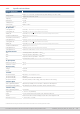
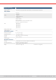
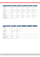
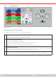
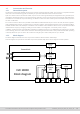
Table Of Contents
- 1. General
- 1.1 About this document
- 1.2 Warranty
- 1.3 Limitation of liability
- 1.4 Disposal of equipment
- 1.5 Product key
- 1.6 Intended usage
- 1.7 Safety
- 1.8 Technical Data
- 1.9 Construction and function
- 1.9.1 General description
- 1.9.2 Block diagram
- 1.9.3 Scope of delivery
- 1.9.4 Accessories
- 1.9.5 Options
- 1.9.6 The control panel (HMI)
- 1.9.7 USB port (rear side)
- 1.9.8 Interface module slot
- 1.9.9 Analog interface
- 1.9.10 “Share BUS” connector
- 1.9.11 “Sense” connector (remote sensing)
- 1.9.12 Master-Slave bus
- 1.9.13 Ethernet port
- 2. Installation & commissioning
- 2.1 Transport and storage
- 2.2 Unpacking and visual check
- 2.3 Installation
- 2.3.1 Safety procedures before installation and use
- 2.3.2 Preparation
- 2.3.3 Installing the device
- 2.3.4 Connection to AC supply
- 2.3.5 Connection to DC sources
- 2.3.6 Connection of remote sensing
- 2.3.7 Grounding of the DC terminal
- 2.3.8 Installation of an interface module
- 2.3.9 Connection of the analog interface
- 2.3.10 Connection of the Share bus
- 2.3.11 Connection of the USB port (rear side)
- 2.3.12 Initial commission
- 2.3.13 Commission after a firmware update or a long period of non-use
- 3. Operation and application
- 3.1 Important notes
- 3.2 Operating modes
- 3.3 Alarm conditions
- 3.4 Manual operation
- 3.5 Remote control
- 3.6 Alarms and monitoring
- 3.7 Locking the control panel (HMI)
- 3.8 Locking the adjustment limits and user profiles
- 3.9 Loading and saving user profiles
- 3.10 The function generator
- 3.10.1 Introduction
- 3.10.2 General
- 3.10.3 Method of operation
- 3.10.4 Manual operation
- 3.10.5 Sine wave function
- 3.10.6 Triangular function
- 3.10.7 Rectangular function
- 3.10.8 Trapezoidal function
- 3.10.9 DIN 40839 function
- 3.10.10 Arbitrary function
- 3.10.11 Ramp function
- 3.10.12 IU table function (XY table)
- 3.10.13 Battery test function
- 3.10.14 MPP tracking function
- 3.10.15 Remote control of the function generator
- 3.11 Other applications
- 4. Service and maintenance
- 5. Contact and support

© EA Elektro-Automatik in 2022, this information is subject to change without notice 1233200840_manual_elr_10000_2u_3kw_en_02
1.8.3 Specic technical data
General speci cations
AC input
Voltage, Phases
Range 1: 110 - 127 V,
±
10%, 1ph AC (with DC input power derating to 1.2 kW or 1.5 kW)
Range 2: 208 - 240 V,
±
10%, 1ph AC
Frequency 45 - 65 Hz
Power factor ca. 0.99
Leakage current <3.5 mA
Inrush current @230 V: ca. 23 A
Overvoltage category 2
DC input static
Load regulation CV ≤0.05% FS
(0 - 100% load, constant input voltage and constant temperature)
Line regulation CV ≤0.01% FS (110 V - 240 V AC
+
10%, constant load and constant temperature)
Stability CV ≤0.02% FS (during 8 h of operation, after 30 minutes warm-up, at constant input voltage, load and temperature)
Temperature coeffi cient CV ≤30ppm/°C (after 30 minutes of warm-up)
Compensation (remote sense) ≤5% U
Nominal
Load regulation CC ≤0.1% FS (0 - 100% load, constant input voltage and constant temperature)
Line regulation CC ≤0.01% FS (110 V - 240 V AC
+
10%, constant load and constant temperature)
Stability CC ≤0.02% FS (during 8 h of operation, after 30 minutes warm-up, at constant input voltage, load and temperature)
Temperature coeffi cient CC ≤50ppm/°C (after 30 minutes of warm-up)
Load regulation CP
≤0.3% FS
(0 - 100% load, constant input voltage and constant temperature)
Load regulation CR ≤0.3% FS + 0.1% FS current (0 - 100% load, constant input voltage and constant temperature)
Protective functions
OVP Overvoltage protection, adjustable 0 - 110% U
Nominal
OCP Overcurrent protection, adjustable 0 - 110% I
Nominal
OPP Overpower protection, adjustable 0 - 110% P
Nominal
OT Overtemperature protection (DC input shuts down in case of insuffi cient cooling)
DC input dynamic
Rise time 10 - 90% CC ≤10 ms
Fall time 90 - 10% CC ≤10 ms
Display accuracy
Voltage ≤0.05% FS
Current ≤0.1% FS
Insulation
AC input to DC input 3750 Vrms
(1 minute, creepage distance >8 mm) *1
AC input to case (PE) 2500 Vrms
DC input to case (PE) Depending on the model, see model tables
DC input to interfaces 1000 V DC (models up to 360 V rating), 1500 V DC (models from 500 V rating)
Interfaces digital
Built-in, galvanically isolated USB, Ethernet (100 MBit) for communication, 1x USB host for data acquisition
Optional, galvanically isolated CAN, CANopen, RS232, ModBus TCP, Profi net, Profi bus, EtherCAT, Ethernet
Interfaces analog
Built-in, galvanically isolated 15 pole D-Sub
Signal range 0 - 10 V or 0 - 5 V (switchable)
Inputs U, I, P, R, remote control on/off, DC input on/off, resistance mode on/off
Outputs Monitor U and I, alarms, reference voltage, DC input status, CV/CC regulation mode
Accuracy U / I / P / R 0 - 10 V: ≤0.2%, 0 - 5: V ≤0.4%
*1 Models with 80 V DC rating have reinforced insulation while all other models from 200 V DC rating have basic insulation