
Manual
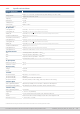
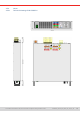
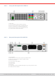
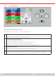
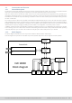
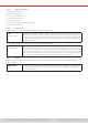
Table Of Contents
- 1. General
- 1.1 About this document
- 1.2 Warranty
- 1.3 Limitation of liability
- 1.4 Disposal of equipment
- 1.5 Product key
- 1.6 Intended usage
- 1.7 Safety
- 1.8 Technical Data
- 1.9 Construction and function
- 1.9.1 General description
- 1.9.2 Block diagram
- 1.9.3 Scope of delivery
- 1.9.4 Accessories
- 1.9.5 Options
- 1.9.6 The control panel (HMI)
- 1.9.7 USB port (rear side)
- 1.9.8 Interface module slot
- 1.9.9 Analog interface
- 1.9.10 “Share BUS” connector
- 1.9.11 “Sense” connector (remote sensing)
- 1.9.12 Master-Slave bus
- 1.9.13 Ethernet port
- 2. Installation & commissioning
- 2.1 Transport and storage
- 2.2 Unpacking and visual check
- 2.3 Installation
- 2.3.1 Safety procedures before installation and use
- 2.3.2 Preparation
- 2.3.3 Installing the device
- 2.3.4 Connection to AC supply
- 2.3.5 Connection to DC sources
- 2.3.6 Connection of remote sensing
- 2.3.7 Grounding of the DC terminal
- 2.3.8 Installation of an interface module
- 2.3.9 Connection of the analog interface
- 2.3.10 Connection of the Share bus
- 2.3.11 Connection of the USB port (rear side)
- 2.3.12 Initial commission
- 2.3.13 Commission after a firmware update or a long period of non-use
- 3. Operation and application
- 3.1 Important notes
- 3.2 Operating modes
- 3.3 Alarm conditions
- 3.4 Manual operation
- 3.5 Remote control
- 3.6 Alarms and monitoring
- 3.7 Locking the control panel (HMI)
- 3.8 Locking the adjustment limits and user profiles
- 3.9 Loading and saving user profiles
- 3.10 The function generator
- 3.10.1 Introduction
- 3.10.2 General
- 3.10.3 Method of operation
- 3.10.4 Manual operation
- 3.10.5 Sine wave function
- 3.10.6 Triangular function
- 3.10.7 Rectangular function
- 3.10.8 Trapezoidal function
- 3.10.9 DIN 40839 function
- 3.10.10 Arbitrary function
- 3.10.11 Ramp function
- 3.10.12 IU table function (XY table)
- 3.10.13 Battery test function
- 3.10.14 MPP tracking function
- 3.10.15 Remote control of the function generator
- 3.11 Other applications
- 4. Service and maintenance
- 5. Contact and support

© EA Elektro-Automatik in 2022, this information is subject to change without notice 1133200840_manual_elr_10000_2u_3kw_en_02
1.8 Technical Data
1.8.1 Approved operating conditions
1. 8 .1.1 Ambiance
The allowed ambient temperature range for operation is 0 °C (32 °F) to 50 °C (122 °F). During storage or transport, the allowed
range extends to -20 °C (-4 °F) to 70 °C (158 °F). In case water condensation occurred due to transport, the device must be
acclimatized prior to operation for at least 2 hours, ideally in a place with good air circulation.
The device is intended to be operation in dry rooms. It must not be exposed or operated to extreme dust, high air humidity,
danger of explosion and aggressive chemicals polluting the air. The operating position isn’t arbitrary (see
“2.3.3. Installing
the device”
),but in any case it requires a sucient air circulation. The device is allowed to be operated in altitude up to 2000
m (approx. 6,560 ft) above sea level. Technical specications (here: ratings), when given with tolerance, are valid for a unit
warmed up for at least 30 minutes and for an ambient temperature of 23 °C (73 °F). Specications without tolerance are
typical values from an average device.
1.8.1.2 Cooling
Power dissipated inside the device heats up air circulating through the device. With the air-cooled versions a fan at the end
of an air ow channel,in which a cooling block is placed, pulls the air through the device. Entry is on the front, exhaust at the
back. Depending on the internal temperature, the fan speed is automatically regulated up or down, whereas a certain minimum
speed is maintained because some internal components even heat up when the device is idle.
Dust in the air can obstruct the air ow with time, thus it’s important to keep the air ow unimpeded at least outside of the device
be leaving sucient room behind it. Since it’s usually installed inside cabinets, the cabinet doors are required to be meshed.
At the same time, the ambient temperature should be kept at low levels, perhaps by external means such as an air condition.
Should the device heat up internally and the cooling block temperature exceed 80 °C (160 °F), the device will protect itself
from overheating by automatically switching off the power stage. It could then only continue to operate and switch the power
stage on again after cooling down for some time.
1.8.2 General technical data
Display: Color TFT touch screen with gorilla glass, 5”, 800pt x 480pt, capacitive
Controls: 2 rotary knobs with pushbutton function, 1 pushbutton