
Manual


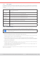
Table Of Contents
- 1. General
- 1.1 About this document
- 1.2 Warranty
- 1.3 Limitation of liability
- 1.4 Disposal of equipment
- 1.5 Product key
- 1.6 Intended usage
- 1.7 Safety
- 1.8 Technical Data
- 1.9 Construction and function
- 1.9.1 General description
- 1.9.2 Block diagram
- 1.9.3 Scope of delivery
- 1.9.4 Accessories
- 1.9.5 Options
- 1.9.6 The control panel (HMI)
- 1.9.7 USB port (rear side)
- 1.9.8 Interface module slot
- 1.9.9 Analog interface
- 1.9.10 “Share BUS” connector
- 1.9.11 “Sense” connector (remote sensing)
- 1.9.12 Master-Slave bus
- 1.9.13 Ethernet port
- 2. Installation & commissioning
- 2.1 Transport and storage
- 2.2 Unpacking and visual check
- 2.3 Installation
- 2.3.1 Safety procedures before installation and use
- 2.3.2 Preparation
- 2.3.3 Installing the device
- 2.3.4 Connection to AC supply
- 2.3.5 Connection to DC sources
- 2.3.6 Connection of remote sensing
- 2.3.7 Grounding of the DC terminal
- 2.3.8 Installation of an interface module
- 2.3.9 Connection of the analog interface
- 2.3.10 Connection of the Share bus
- 2.3.11 Connection of the USB port (rear side)
- 2.3.12 Initial commission
- 2.3.13 Commission after a firmware update or a long period of non-use
- 3. Operation and application
- 3.1 Important notes
- 3.2 Operating modes
- 3.3 Alarm conditions
- 3.4 Manual operation
- 3.5 Remote control
- 3.6 Alarms and monitoring
- 3.7 Locking the control panel (HMI)
- 3.8 Locking the adjustment limits and user profiles
- 3.9 Loading and saving user profiles
- 3.10 The function generator
- 3.10.1 Introduction
- 3.10.2 General
- 3.10.3 Method of operation
- 3.10.4 Manual operation
- 3.10.5 Sine wave function
- 3.10.6 Triangular function
- 3.10.7 Rectangular function
- 3.10.8 Trapezoidal function
- 3.10.9 DIN 40839 function
- 3.10.10 Arbitrary function
- 3.10.11 Ramp function
- 3.10.12 IU table function (XY table)
- 3.10.13 Battery test function
- 3.10.14 MPP tracking function
- 3.10.15 Remote control of the function generator
- 3.11 Other applications
- 4. Service and maintenance
- 5. Contact and support

© EA Elektro-Automatik in 2022, this information is subject to change without notice 1033200840_manual_elr_10000_2u_3kw_en_02
1.7.5 Alarm signals
The equipment offers various possibilities for signaling alarm conditions, however, not for danger situations. The signals may
be optical (on the display as text or via LED), acoustic (piezo buzzer) or electronic (pin/status output of an analog interface).
All alarms will cause the device to switch off the DC input. For details about the different alarms refer to section
“3.3. Alarm
conditions”
.
The meaning of the signals is as follows:
Signal OT
(OverTemperature)
• Overheating of the device
• DC input will be switched off
• Non-critical
Signal OVP / SOVP
(OverVoltage)
• Overvoltage shutdown of the DC input due to high voltage coming onto the device
• Critical! The device and/or the source could be damaged
Signal OCP
(OverCurrent)
• Shutdown of the DC input due to excess of the preset limit
• Non-critical, protects the source from feeding excessive current
Signal OPP
(OverPower)
• Shutdown of the DC input due to excess of the preset limit
• Non-critical, protects the source from feeding excessive power
Signal PF
(Power Fail)
• DC input shutdown due to AC undervoltage or defect in the AC section
• Critical on overvoltage! AC section could be damaged
Signal MSP
(Master-Slave Pro-
tection)
• DC input shutdown due to communication problems on the master-slave bus
• Non-critical
Signal SF
(Share Bus Fail)
• DC input shutdown due to signal distortion on the Share bus
• Non-critical
1.7.6 Functionality test
The operator of the device must decide when to check the device for correct functionality, by whom and how often. The when
could either be before every use or after it has been relocated or recongured or perhaps in a dened interval.
Should the set values not be adjustable as instructed below it could simply be due to adjustment limits
interfering. See “3.4.4. Adjustment limits”. When reaching a limit when adjusting value, the device would
indicate in the display.
The test procedure would always be like this:
1. Disconnect all cables (Sense, Share bus, analog interface, USB), except for AC
2. Connect an external DC source that can at least deliver as much current and voltage as the rating of the device under
test (DUT) and set it to 10% U
Nom
current of the DUT and full
3. Connect a suitable ampere meter (shunt, current transducer) in line with or around one of the DC cables
4. Switch the device on, adjust a current of 10% I
Nom
while the voltage set value is set to 0 and the power set values to
maximum. Then switch the DC input on and measure the current with the ammeter and compare. Also check what the
actual current on the display shows.
5. Repeat the same thing at 100% U
Nom
.
6. Should the external DC source be adjustable in current, limit the current to 90% INom of the DUT while setting the
voltage to 102% U
Nom
of the DUT. Add a voltage multimeter on the DC input.
7. On the DUT, adjust 10% U
Nom
and measure with the multimeter on the DC input to verify the adjusted voltage is met.
Also check what the actual current on the display shows.
8. Repeat the same thing at 90% or 100% U
Nom
.
Only if the current and voltage are supplied by the device as adjustable in the range of 0-100% FS, the device can be consid-
ered as correctly operational.