
User manual


35
© 2009, Elektro-Automatik GmbH & Co. KG
EN
About the power supply
3. Device description
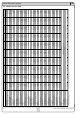
3.1 Views
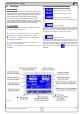
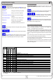
Figure 1. Front view
Figure 2. Rear view
Legend: Pin assigment of System Bus:
A - Power switch (pins 3-8 only available at models from 1kW)
B - Control panel 1 - Sense +
C - Power output 2 - Sense -
D - Analogue interface, 15pole, female 3 - Master output Current
E - Slot for digital extension cards 4 - Master output Voltage
F - System Bus 5 - Slave input Current
G - Fan 6 - Slave input Voltage
H-Inputfuse(forvaluesee„Technicalspecications“) 7-ShareBus
J - Power input socket, 3pole, IEC 60320 8 - Ground