
User manual


Table Of Contents
- 06230304_MA-PSI9000-2U-TFT-DE
- 1. Allgemeines
- 1.1 Zu diesem Dokument
- 1.2 Gewährleistung und Garantie
- 1.3 Haftungsbeschränkungen
- 1.4 Entsorgung des Gerätes
- 1.5 Produktschlüssel
- 1.6 Bestimmungsgemäße Verwendung
- 1.7 Sicherheit
- 1.8 Technische Daten
- 1.9 Aufbau und Funktion
- 1.9.1 Allgemeine Beschreibung
- 1.9.2 Blockdiagramm
- 1.9.3 Lieferumfang
- 1.9.4 Zubehör
- 1.9.5 Optionen
- 1.9.6 Die Bedieneinheit (HMI)
- 1.9.7 USB-Port (Rückseite)
- 1.9.8 Steckplatz für Schnittstellenmodule
- 1.9.9 Analogschnittstelle
- 1.9.10 Share-Bus-Anschluß
- 1.9.11 Sense-Anschluß (Fernfühlung)
- 1.9.12 Master-Slave-Bus
- 1.9.13 GPIB-Port (optional)
- 2. Installation & Inbetriebnahme
- 2.1 Transport und Lagerung
- 2.2 Auspacken und Sichtkontrolle
- 2.3 Installation
- 2.3.1 Sicherheitsmaßnahmen vor Installation und Gebrauch
- 2.3.2 Vorbereitung
- 2.3.3 Aufstellung des Gerätes
- 2.3.4 Anschließen an das Stromnetz (AC)
- 2.3.5 Anschließen von DC-Lasten
- 2.3.6 Erdung des DC-Ausgangs
- 2.3.7 Anschließen der Fernfühlung
- 2.3.8 Installation eines AnyBus-Schnittstellenmoduls
- 2.3.9 Anschließen der analogen Schnittstelle
- 2.3.10 Anschließen des „Share-Bus“
- 2.3.11 Anschließen des USB-Ports (Rückseite)
- 2.3.12 Erstinbetriebnahme
- 2.3.13 Erneute Inbetriebnahme nach Firmwareupdates bzw. längerer Nichtbenutzung
- 3. Bedienung und Verwendung
- 3.1 Personenschutz
- 3.2 Regelungsarten
- 3.3 Alarmzustände
- 3.4 Manuelle Bedienung
- 3.5 Fernsteuerung
- 3.6 Alarme und Überwachung
- 3.7 Bedieneinheit (HMI) sperren
- 3.8 Nutzerprofile laden und speichern
- 3.9 Der Funktionsgenerator
- 3.9.1 Einleitung
- 3.9.2 Allgemeines
- 3.9.3 Arbeitsweise
- 3.9.4 Manuelle Bedienung
- 3.9.5 Sinus-Funktion
- 3.9.6 Dreieck-Funktion
- 3.9.7 Rechteck-Funktion
- 3.9.8 Trapez-Funktion
- 3.9.9 DIN 40839-Funktion
- 3.9.10 Arbiträr-Funktion
- 3.9.11 Rampen-Funktion
- 3.9.12 UI- und IU-Tabellenfunktion (XY-Tabelle)
- 3.9.13 PV-Tabellenfunktion (Photovoltaik)
- 3.9.14 FC-Tabellenfunktion (Brennstoffzelle)
- 3.9.15 Fernsteuerung des Funktionsgenerators
- 3.10 Weitere Anwendungen
- 4. Instandhaltung & Wartung
- 5. Zubehör und Optionen
- 6. Service & Support
- 1. Allgemeines
- 06230304_MA-PSI9000-2U-TFT-EN
- 1. General
- 1.1 About this document
- 1.2 Warranty
- 1.3 Limitation of liability
- 1.4 Disposal of equipment
- 1.5 Product key
- 1.6 Intended usage
- 1.7 Safety
- 1.8 Technical Data
- 1.9 Construction and function
- 1.9.1 General description
- 1.9.2 Block diagram
- 1.9.3 Scope of delivery
- 1.9.4 Accessories
- 1.9.5 Options
- 1.9.6 The control panel (HMI)
- 1.9.7 USB port (rear side)
- 1.9.8 Interface module slot
- 1.9.9 Analog interface
- 1.9.10 Share Bus-Connection
- 1.9.11 Sense connector (remote sensing)
- 1.9.12 Master-Slave bus
- 1.9.13 GPIB port (optional)
- 2. Installation & commissioning
- 2.1 Transport and storage
- 2.2 Unpacking and visual check
- 2.3 Installation
- 2.3.1 Safety procedures before installation and use
- 2.3.2 Preparation
- 2.3.3 Installing the device
- 2.3.4 Connection to AC supply
- 2.3.5 Connection to DC loads
- 2.3.6 Grounding of the DC output
- 2.3.7 Connection of remote sensing
- 2.3.8 Installation of an AnyBus interface module
- 2.3.9 Connecting the analog interface
- 2.3.10 Connecting the “Share” bus
- 2.3.11 Connecting the USB port (rear side)
- 2.3.12 Initial commission
- 2.3.13 Commission after a firmware update or a long period of non-use
- 3. Operation and application
- 3.1 Personal safety
- 3.2 Operating modes
- 3.3 Alarm conditions
- 3.4 Manual operation
- 3.5 Remote control
- 3.6 Alarms and monitoring
- 3.7 Control panel (HMI) lock
- 3.8 Loading and saving a user profile
- 3.9 The function generator
- 3.9.1 Introduction
- 3.9.2 General
- 3.9.3 Method of operation
- 3.9.4 Manual operation
- 3.9.5 Sine wave function
- 3.9.6 Triangular function
- 3.9.7 Rectangular function
- 3.9.8 Trapezoidal function
- 3.9.9 DIN 40839 function
- 3.9.10 Arbitrary function
- 3.9.11 Ramp Function
- 3.9.12 UI and IU table functions (XY table)
- 3.9.13 PV table function (photovoltaics)
- 3.9.14 FC table function (fuel cell)
- 3.9.15 Remote control of the function generator
- 3.10 Other applications
- 4. Service and maintenance
- 5. Accessories and options
- 6. Service & Support
- 1. General
Page 70
PSI 9000 2U Series
www.elektroautomatik.de
ea1974@elektroautomatik.de
EA Elektro-Automatik GmbH
Helmholtzstr. 31-33 • 41747 Viersen
Germany
Fon: +49 2162 / 3785-0
Fax: +49 2162 / 16230
3.9.10.1 Loading and saving the arbitrary function
The 100 sequences of the arbitrary function, which can be manually congured with the control panel of the device
and which are applicable either to voltage (U) or current (I), can be saved to or loaded from a common USB ash
drive via the front side USB port. Generally, all 100 sequences are saved or loaded using a text le of type CSV
(semicolon separator), which represents a table of values.
In order to load a sequence table for the arbitrary generator, following requirements have to be met:
• The table must contain exactly 100 rows with 8 subsequent values (8 columns, separated by semicolons) and
must not have gaps
• The les must be stored inside a folder called HMI_FILES which has to be in the root of the USB drive
• The le name must always start with WAVE_U or WAVE_I (not case-sensitive)
• Values with decimal places must use the comma as decimal separator
• All values in every row and column have to be within the specied range (see below)
• The columns in the table have to be in a dened order which must not be changed
Following value ranges are given for use in the table, related to the manual conguration of the arbitrary generator
(column headers like in Excel):
Column Parameter Range
A AC Start 0...50% U or I
B AC End 0...50% U or I
C Frequency Start 0...1000 Hz
D Frequency End 0...1000 Hz
E Start angle AC 0...359°
F DC Start 0...(Nominal value of U or I) - AC Start
G DC End 0...(Nominal value of U or I) - AC End
H Time in μs 100...36.000.000.000 (36 billion μs)
For details about the parameter and the arbitrary function refer to „3.9.10. Arbitrary function“.
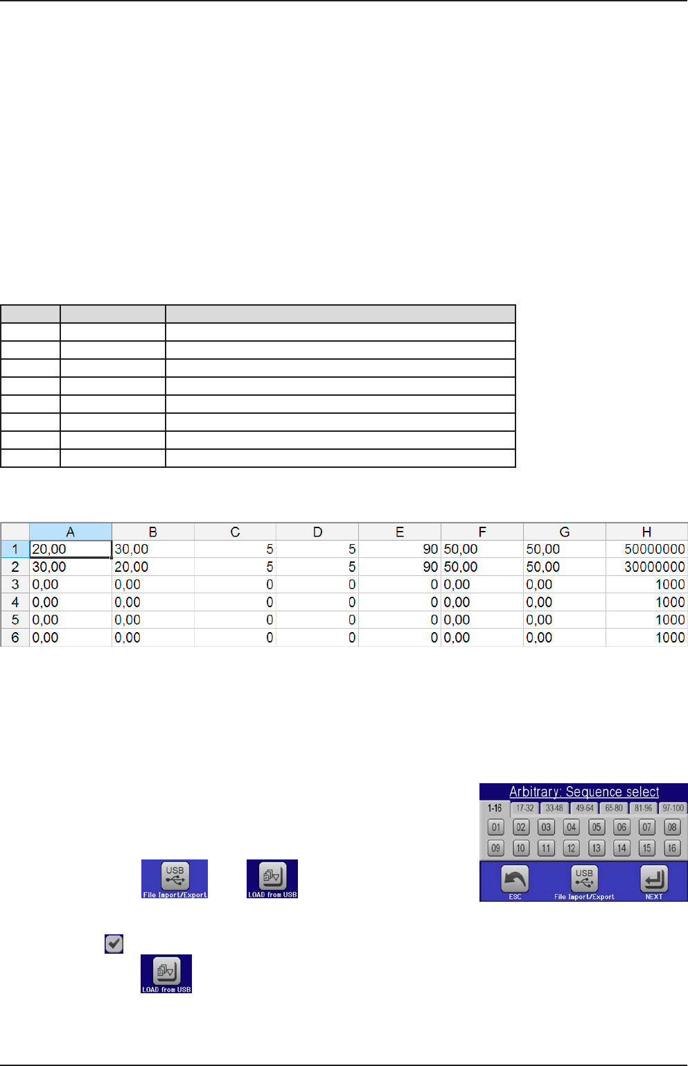
Example CSV:
The example shows that only the rst two sequences are congured, while all others are set to default values. The
table could be loaded as WAVE_U or WAVE_I when using, for example, the model PSI 9080-120 2U, because the
values would t both, voltage and current. The le naming, however, is unique. A lter prevents you from loading
a WAVE_I le after you have selected “Arbitrary --> U” in the function generator menu. The le would not be listed
as selectable at all.
► How to load a sequence table (100 sequences) from a USB ash drive:
1. Do not plug the USB drive yet or remove it.
2. Access the function selection menu of the function generator with
MENU -> Function Generator -> Arbitrary -> U/I, to see the main screen
of sequence selector, as depicted to the right.
3. Tap touch area , then and follow the instructions
on screen. If at least one valid les has been recognized (for le and
path naming see above), the device will show a list of les to select
from with .
4. Tap touch area in the bottom right corner. The selected le is then checked and loaded, if valid.
In case it is not valid, the device will show an error message. Then the le must be corrected and the
steps repeated.