
User manual


Table Of Contents
- 06230304_MA-PSI9000-2U-TFT-DE
- 1. Allgemeines
- 1.1 Zu diesem Dokument
- 1.2 Gewährleistung und Garantie
- 1.3 Haftungsbeschränkungen
- 1.4 Entsorgung des Gerätes
- 1.5 Produktschlüssel
- 1.6 Bestimmungsgemäße Verwendung
- 1.7 Sicherheit
- 1.8 Technische Daten
- 1.9 Aufbau und Funktion
- 1.9.1 Allgemeine Beschreibung
- 1.9.2 Blockdiagramm
- 1.9.3 Lieferumfang
- 1.9.4 Zubehör
- 1.9.5 Optionen
- 1.9.6 Die Bedieneinheit (HMI)
- 1.9.7 USB-Port (Rückseite)
- 1.9.8 Steckplatz für Schnittstellenmodule
- 1.9.9 Analogschnittstelle
- 1.9.10 Share-Bus-Anschluß
- 1.9.11 Sense-Anschluß (Fernfühlung)
- 1.9.12 Master-Slave-Bus
- 1.9.13 GPIB-Port (optional)
- 2. Installation & Inbetriebnahme
- 2.1 Transport und Lagerung
- 2.2 Auspacken und Sichtkontrolle
- 2.3 Installation
- 2.3.1 Sicherheitsmaßnahmen vor Installation und Gebrauch
- 2.3.2 Vorbereitung
- 2.3.3 Aufstellung des Gerätes
- 2.3.4 Anschließen an das Stromnetz (AC)
- 2.3.5 Anschließen von DC-Lasten
- 2.3.6 Erdung des DC-Ausgangs
- 2.3.7 Anschließen der Fernfühlung
- 2.3.8 Installation eines AnyBus-Schnittstellenmoduls
- 2.3.9 Anschließen der analogen Schnittstelle
- 2.3.10 Anschließen des „Share-Bus“
- 2.3.11 Anschließen des USB-Ports (Rückseite)
- 2.3.12 Erstinbetriebnahme
- 2.3.13 Erneute Inbetriebnahme nach Firmwareupdates bzw. längerer Nichtbenutzung
- 3. Bedienung und Verwendung
- 3.1 Personenschutz
- 3.2 Regelungsarten
- 3.3 Alarmzustände
- 3.4 Manuelle Bedienung
- 3.5 Fernsteuerung
- 3.6 Alarme und Überwachung
- 3.7 Bedieneinheit (HMI) sperren
- 3.8 Nutzerprofile laden und speichern
- 3.9 Der Funktionsgenerator
- 3.9.1 Einleitung
- 3.9.2 Allgemeines
- 3.9.3 Arbeitsweise
- 3.9.4 Manuelle Bedienung
- 3.9.5 Sinus-Funktion
- 3.9.6 Dreieck-Funktion
- 3.9.7 Rechteck-Funktion
- 3.9.8 Trapez-Funktion
- 3.9.9 DIN 40839-Funktion
- 3.9.10 Arbiträr-Funktion
- 3.9.11 Rampen-Funktion
- 3.9.12 UI- und IU-Tabellenfunktion (XY-Tabelle)
- 3.9.13 PV-Tabellenfunktion (Photovoltaik)
- 3.9.14 FC-Tabellenfunktion (Brennstoffzelle)
- 3.9.15 Fernsteuerung des Funktionsgenerators
- 3.10 Weitere Anwendungen
- 4. Instandhaltung & Wartung
- 5. Zubehör und Optionen
- 6. Service & Support
- 1. Allgemeines
- 06230304_MA-PSI9000-2U-TFT-EN
- 1. General
- 1.1 About this document
- 1.2 Warranty
- 1.3 Limitation of liability
- 1.4 Disposal of equipment
- 1.5 Product key
- 1.6 Intended usage
- 1.7 Safety
- 1.8 Technical Data
- 1.9 Construction and function
- 1.9.1 General description
- 1.9.2 Block diagram
- 1.9.3 Scope of delivery
- 1.9.4 Accessories
- 1.9.5 Options
- 1.9.6 The control panel (HMI)
- 1.9.7 USB port (rear side)
- 1.9.8 Interface module slot
- 1.9.9 Analog interface
- 1.9.10 Share Bus-Connection
- 1.9.11 Sense connector (remote sensing)
- 1.9.12 Master-Slave bus
- 1.9.13 GPIB port (optional)
- 2. Installation & commissioning
- 2.1 Transport and storage
- 2.2 Unpacking and visual check
- 2.3 Installation
- 2.3.1 Safety procedures before installation and use
- 2.3.2 Preparation
- 2.3.3 Installing the device
- 2.3.4 Connection to AC supply
- 2.3.5 Connection to DC loads
- 2.3.6 Grounding of the DC output
- 2.3.7 Connection of remote sensing
- 2.3.8 Installation of an AnyBus interface module
- 2.3.9 Connecting the analog interface
- 2.3.10 Connecting the “Share” bus
- 2.3.11 Connecting the USB port (rear side)
- 2.3.12 Initial commission
- 2.3.13 Commission after a firmware update or a long period of non-use
- 3. Operation and application
- 3.1 Personal safety
- 3.2 Operating modes
- 3.3 Alarm conditions
- 3.4 Manual operation
- 3.5 Remote control
- 3.6 Alarms and monitoring
- 3.7 Control panel (HMI) lock
- 3.8 Loading and saving a user profile
- 3.9 The function generator
- 3.9.1 Introduction
- 3.9.2 General
- 3.9.3 Method of operation
- 3.9.4 Manual operation
- 3.9.5 Sine wave function
- 3.9.6 Triangular function
- 3.9.7 Rectangular function
- 3.9.8 Trapezoidal function
- 3.9.9 DIN 40839 function
- 3.9.10 Arbitrary function
- 3.9.11 Ramp Function
- 3.9.12 UI and IU table functions (XY table)
- 3.9.13 PV table function (photovoltaics)
- 3.9.14 FC table function (fuel cell)
- 3.9.15 Remote control of the function generator
- 3.10 Other applications
- 4. Service and maintenance
- 5. Accessories and options
- 6. Service & Support
- 1. General
Page 67
EA Elektro-Automatik GmbH
Helmholtzstr. 31-33 • 41747 Viersen
Germany
Fon: +49 2162 / 3785-0
Fax: +49 2162 / 16230
www.elektroautomatik.de
ea1974@elektroautomatik.de
PSI 9000 2U Series
3.9.10 Arbitrary function
The arbitrary (freely denable) function offers the user further scope. Up to 100 sequences are available for use
for current I and voltage U, all of which have the same parameters but which can be differently congured so that
a complex function process can be built up. The 100 sequences can run one after another in a sequence block,
and this sequence block can then be repeated many times or endlessly. From the 100 sequences a block can be
freely dened to run from sequence x to sequence y. A sequence or sequence block acts only on current or volt-
age, thus a mix of assignment to current I or voltage U is not possible.
The arbitrary curve overlays a linear progression (DC) with a sine curve (AC), whose amplitude and frequency
are shaped between start and end values. If the start frequency (fs) = end frequency (fe) = 0 Hz, the AC values
have no impact and only the DC part is effective. Each sequence is allocated a sequence time in which the AC/
DC curve from start to nish will be generated.
The following parameters can be congured for each sequence in the arbitrary function (the table lists parameters
for current, for voltage it would be Us, Ue etc.)
Value Range Seq. Description
Is(AC) 0...50% Nominal value I 1-100 Start amplitude of the sine wave part of the curve
Ie(AC) 0...50% Nominal value I 1-100 End amplitude of the sine wave part of the curve
fs(1/T) 0 Hz...10000 Hz 1-100 Start frequency of the sine wave part of the curve (AC)
fe(1/T) 0 Hz...10000 Hz 1-100 End frequency of the sine wave part of the curve (AC)
Angle 0°...359° 1-100 Start angle of the sine wave part of the curve (AC)
Is(DC) Is(AC)...(Nominal value - Is(AC)) of I 1-100 Start value of the DC part of the curve
Ie(DC) Ie(AC)...(Nominal value - Ie(AC)) of I 1-100 End value of the DC part of the curve
Seq.time 0.1 ms...36000 s 1-100 Time for the selected sequence
The sequence time (seq. time) and the start and end frequency are related. The minimum value
for Δf/s is 9.3. Thus, for example, a setting of fs = 1 Hz, fe = 11 Hz and Seq.time = 5 s would
not be accepted as Δf/s is only 2. A seq. time of 1 s would be accepted, or, if the time remains
at 5 s, then fe = 51 Hz must be set.
The amplitude change between start and end is related to the sequence time. A minimal change
over an extended time is not possible and in such a case the device will report an inapplicable
setting.
After the settings for the selected sequence are accepted with SAVE, further sequences can be congured. If
the button NEXT is touched a second settings screen appears in which global settings for all 100 sequences are
displayed.
The following parameters can be set for the total run of an arbitrary function:
Value Range Description
Start seq. 1...End seq. First sequence in the sequence block
End seq. 100...Start seq. Last sequence in the sequence block
Seq. Cycles ∞ orr 1...999 Number of cycles of the sequence block.
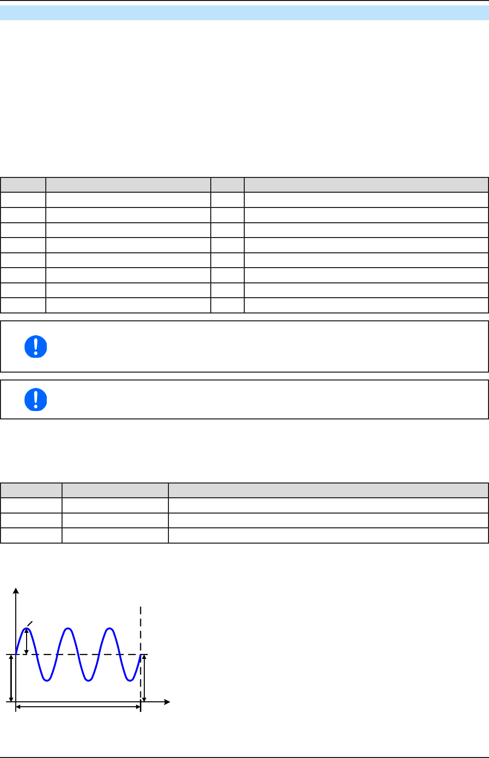
Schematic diagram: Applications and results:
Start (DC)
t
A
Start (AC)
Seq.time
End (DC)
Example 1
Focussing 1 cycle of 1 sequence from 100:
DC values for start and end are the same, also the AC amplitude.
With a frequency >0 a sine wave progression of the set value is
generated with a dened amplitude, frequency and Y-shift (offset,
DC value at start and end)
The number of sine waves per cycle depend on the sequence time
and the frequency. If the sequence time were 1 s and the frequency
1 Hz, there would be exactly 1 sine wave. If the time were 0.5 s at
the same frequency, there would only be a half sine wave.