
User manual


Table Of Contents
- 06230304_MA-PSI9000-2U-TFT-DE
- 1. Allgemeines
- 1.1 Zu diesem Dokument
- 1.2 Gewährleistung und Garantie
- 1.3 Haftungsbeschränkungen
- 1.4 Entsorgung des Gerätes
- 1.5 Produktschlüssel
- 1.6 Bestimmungsgemäße Verwendung
- 1.7 Sicherheit
- 1.8 Technische Daten
- 1.9 Aufbau und Funktion
- 1.9.1 Allgemeine Beschreibung
- 1.9.2 Blockdiagramm
- 1.9.3 Lieferumfang
- 1.9.4 Zubehör
- 1.9.5 Optionen
- 1.9.6 Die Bedieneinheit (HMI)
- 1.9.7 USB-Port (Rückseite)
- 1.9.8 Steckplatz für Schnittstellenmodule
- 1.9.9 Analogschnittstelle
- 1.9.10 Share-Bus-Anschluß
- 1.9.11 Sense-Anschluß (Fernfühlung)
- 1.9.12 Master-Slave-Bus
- 1.9.13 GPIB-Port (optional)
- 2. Installation & Inbetriebnahme
- 2.1 Transport und Lagerung
- 2.2 Auspacken und Sichtkontrolle
- 2.3 Installation
- 2.3.1 Sicherheitsmaßnahmen vor Installation und Gebrauch
- 2.3.2 Vorbereitung
- 2.3.3 Aufstellung des Gerätes
- 2.3.4 Anschließen an das Stromnetz (AC)
- 2.3.5 Anschließen von DC-Lasten
- 2.3.6 Erdung des DC-Ausgangs
- 2.3.7 Anschließen der Fernfühlung
- 2.3.8 Installation eines AnyBus-Schnittstellenmoduls
- 2.3.9 Anschließen der analogen Schnittstelle
- 2.3.10 Anschließen des „Share-Bus“
- 2.3.11 Anschließen des USB-Ports (Rückseite)
- 2.3.12 Erstinbetriebnahme
- 2.3.13 Erneute Inbetriebnahme nach Firmwareupdates bzw. längerer Nichtbenutzung
- 3. Bedienung und Verwendung
- 3.1 Personenschutz
- 3.2 Regelungsarten
- 3.3 Alarmzustände
- 3.4 Manuelle Bedienung
- 3.5 Fernsteuerung
- 3.6 Alarme und Überwachung
- 3.7 Bedieneinheit (HMI) sperren
- 3.8 Nutzerprofile laden und speichern
- 3.9 Der Funktionsgenerator
- 3.9.1 Einleitung
- 3.9.2 Allgemeines
- 3.9.3 Arbeitsweise
- 3.9.4 Manuelle Bedienung
- 3.9.5 Sinus-Funktion
- 3.9.6 Dreieck-Funktion
- 3.9.7 Rechteck-Funktion
- 3.9.8 Trapez-Funktion
- 3.9.9 DIN 40839-Funktion
- 3.9.10 Arbiträr-Funktion
- 3.9.11 Rampen-Funktion
- 3.9.12 UI- und IU-Tabellenfunktion (XY-Tabelle)
- 3.9.13 PV-Tabellenfunktion (Photovoltaik)
- 3.9.14 FC-Tabellenfunktion (Brennstoffzelle)
- 3.9.15 Fernsteuerung des Funktionsgenerators
- 3.10 Weitere Anwendungen
- 4. Instandhaltung & Wartung
- 5. Zubehör und Optionen
- 6. Service & Support
- 1. Allgemeines
- 06230304_MA-PSI9000-2U-TFT-EN
- 1. General
- 1.1 About this document
- 1.2 Warranty
- 1.3 Limitation of liability
- 1.4 Disposal of equipment
- 1.5 Product key
- 1.6 Intended usage
- 1.7 Safety
- 1.8 Technical Data
- 1.9 Construction and function
- 1.9.1 General description
- 1.9.2 Block diagram
- 1.9.3 Scope of delivery
- 1.9.4 Accessories
- 1.9.5 Options
- 1.9.6 The control panel (HMI)
- 1.9.7 USB port (rear side)
- 1.9.8 Interface module slot
- 1.9.9 Analog interface
- 1.9.10 Share Bus-Connection
- 1.9.11 Sense connector (remote sensing)
- 1.9.12 Master-Slave bus
- 1.9.13 GPIB port (optional)
- 2. Installation & commissioning
- 2.1 Transport and storage
- 2.2 Unpacking and visual check
- 2.3 Installation
- 2.3.1 Safety procedures before installation and use
- 2.3.2 Preparation
- 2.3.3 Installing the device
- 2.3.4 Connection to AC supply
- 2.3.5 Connection to DC loads
- 2.3.6 Grounding of the DC output
- 2.3.7 Connection of remote sensing
- 2.3.8 Installation of an AnyBus interface module
- 2.3.9 Connecting the analog interface
- 2.3.10 Connecting the “Share” bus
- 2.3.11 Connecting the USB port (rear side)
- 2.3.12 Initial commission
- 2.3.13 Commission after a firmware update or a long period of non-use
- 3. Operation and application
- 3.1 Personal safety
- 3.2 Operating modes
- 3.3 Alarm conditions
- 3.4 Manual operation
- 3.5 Remote control
- 3.6 Alarms and monitoring
- 3.7 Control panel (HMI) lock
- 3.8 Loading and saving a user profile
- 3.9 The function generator
- 3.9.1 Introduction
- 3.9.2 General
- 3.9.3 Method of operation
- 3.9.4 Manual operation
- 3.9.5 Sine wave function
- 3.9.6 Triangular function
- 3.9.7 Rectangular function
- 3.9.8 Trapezoidal function
- 3.9.9 DIN 40839 function
- 3.9.10 Arbitrary function
- 3.9.11 Ramp Function
- 3.9.12 UI and IU table functions (XY table)
- 3.9.13 PV table function (photovoltaics)
- 3.9.14 FC table function (fuel cell)
- 3.9.15 Remote control of the function generator
- 3.10 Other applications
- 4. Service and maintenance
- 5. Accessories and options
- 6. Service & Support
- 1. General
Page 59
EA Elektro-Automatik GmbH
Helmholtzstr. 31-33 • 41747 Viersen
Germany
Fon: +49 2162 / 3785-0
Fax: +49 2162 / 16230
www.elektroautomatik.de
ea1974@elektroautomatik.de
PSI 9000 2U Series
3.6 Alarms and monitoring
3.6.1 Denition of terms
There is a clear distinction between device alarms (see „3.3. Alarm conditions“) such as overvoltage protection
or overheating protection, and user dened events such as OVD (overvoltage detection). Whilst device alarms
serve to protect the device and the connected load by initially switching off the DC output, user dened events can
switch off the DC output (Action = ALARM), but can also simply give an acoustic signal to make the user aware.
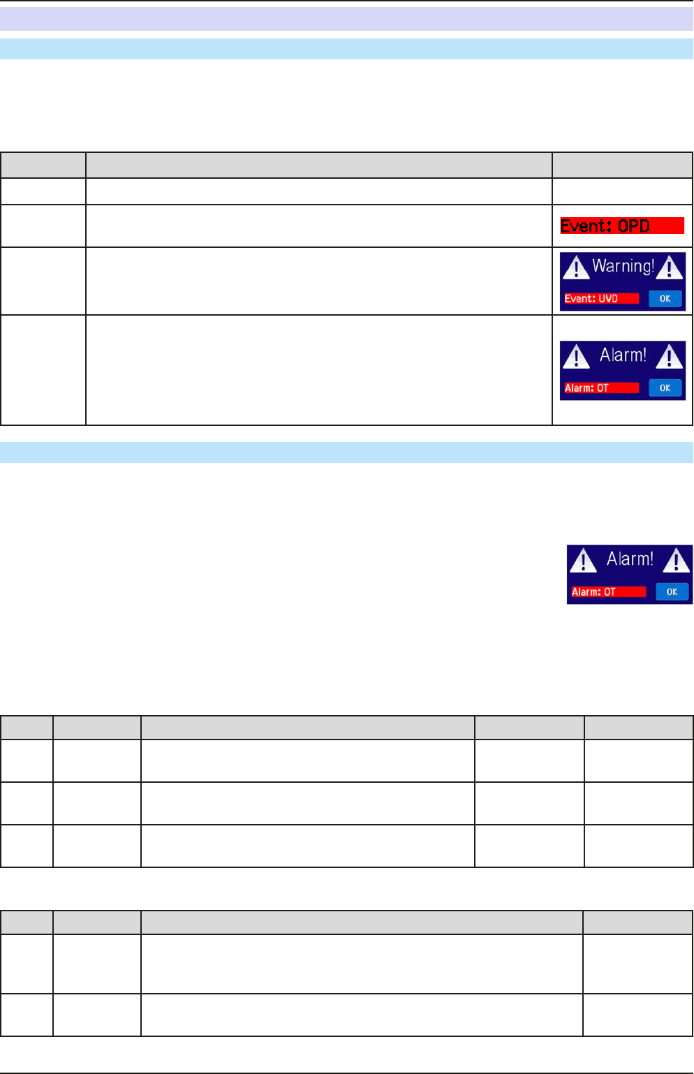
The actions driven by user dened events can be selected:
Action Impact Example
NONE User dened event is disabled.
SIGNAL
On reaching the condition which triggers the event, the action SIGNAL will
show a text message in the status area of the display.
WARNING
On reaching the condition which triggers the event, the action WARNING
will show a text message in the status area of the display and pop up an
additional warning message.
ALARM
On reaching the condition which triggers the event, the action ALARM will
show a text message in the status area of the display with an additional alarm
pop-up, and additionally emit an acoustic signal (if activated). Furthermore
the DC output is switched off. Certain device alarms are also signalled to
the analog interface or can be queried via the digital interface.
3.6.2 Device alarm and event handling
A device alarm incident will usually lead to DC output switch-off, the appearance of a pop-up in the middle of the
display and, if activated, an acoustic signal to make the user aware. The alarm must always be acknowledged.
► How to acknowledge an alarm in the display
1. If the alarm is indicated as a pop-up, tap OK.
2. If the alarm has already been acknowledged, but is still displayed in the status area,
then rst tap the status area to display the pop-up, and then acknowledge with OK.
In order to acknowledge an alarm during analog remote control, see „3.5.4.4. Overview of the Sub-D Socket“. To
acknowledge in digital remote, refer to the external documentation “Programming ModBus & SCPI”.
Some device alarms are congurable:
Alarm Meaning Description Range Indication
OVP
OverVoltage
Protection
Triggers an alarm if the DC output voltage reaches the
dened threshold. The DC output will be switched off.
0 V...1.1*U
Nom
Display, analog
IF, digital IF
OCP
OverCurrent
Protection
Triggers an alarm if the DC output current reaches the
dened threshold. The DC output will be switched off.
0 A...1.1*I
Nom
Display, digital
IF
OPP
OverPower
Protection
Triggers an alarm if the DC output power reaches the
dened threshold. The DC output will be switched off.
0 W...1.1*P
Nom
Display, digital
IF
These device alarms can’t be congured and are based on hardware:
Alarm Meaning Description Indication
PF Power Fail
AC supply over- or undervoltage. Triggers an alarm if the AC supply is out
of specication or when the device is cut from supply, for example when
switching it off with the power switch. The DC output will be switched off.
Display, digital
IF
OT
OverTem-
perature
Triggers an alarm if the internal temperature reaches a certain limit. The
DC output will be switched off.
Display, analog
IF, digital IF