
User manual


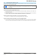


Table Of Contents
- 06230304_MA-PSI9000-2U-TFT-DE
- 1. Allgemeines
- 1.1 Zu diesem Dokument
- 1.2 Gewährleistung und Garantie
- 1.3 Haftungsbeschränkungen
- 1.4 Entsorgung des Gerätes
- 1.5 Produktschlüssel
- 1.6 Bestimmungsgemäße Verwendung
- 1.7 Sicherheit
- 1.8 Technische Daten
- 1.9 Aufbau und Funktion
- 1.9.1 Allgemeine Beschreibung
- 1.9.2 Blockdiagramm
- 1.9.3 Lieferumfang
- 1.9.4 Zubehör
- 1.9.5 Optionen
- 1.9.6 Die Bedieneinheit (HMI)
- 1.9.7 USB-Port (Rückseite)
- 1.9.8 Steckplatz für Schnittstellenmodule
- 1.9.9 Analogschnittstelle
- 1.9.10 Share-Bus-Anschluß
- 1.9.11 Sense-Anschluß (Fernfühlung)
- 1.9.12 Master-Slave-Bus
- 1.9.13 GPIB-Port (optional)
- 2. Installation & Inbetriebnahme
- 2.1 Transport und Lagerung
- 2.2 Auspacken und Sichtkontrolle
- 2.3 Installation
- 2.3.1 Sicherheitsmaßnahmen vor Installation und Gebrauch
- 2.3.2 Vorbereitung
- 2.3.3 Aufstellung des Gerätes
- 2.3.4 Anschließen an das Stromnetz (AC)
- 2.3.5 Anschließen von DC-Lasten
- 2.3.6 Erdung des DC-Ausgangs
- 2.3.7 Anschließen der Fernfühlung
- 2.3.8 Installation eines AnyBus-Schnittstellenmoduls
- 2.3.9 Anschließen der analogen Schnittstelle
- 2.3.10 Anschließen des „Share-Bus“
- 2.3.11 Anschließen des USB-Ports (Rückseite)
- 2.3.12 Erstinbetriebnahme
- 2.3.13 Erneute Inbetriebnahme nach Firmwareupdates bzw. längerer Nichtbenutzung
- 3. Bedienung und Verwendung
- 3.1 Personenschutz
- 3.2 Regelungsarten
- 3.3 Alarmzustände
- 3.4 Manuelle Bedienung
- 3.5 Fernsteuerung
- 3.6 Alarme und Überwachung
- 3.7 Bedieneinheit (HMI) sperren
- 3.8 Nutzerprofile laden und speichern
- 3.9 Der Funktionsgenerator
- 3.9.1 Einleitung
- 3.9.2 Allgemeines
- 3.9.3 Arbeitsweise
- 3.9.4 Manuelle Bedienung
- 3.9.5 Sinus-Funktion
- 3.9.6 Dreieck-Funktion
- 3.9.7 Rechteck-Funktion
- 3.9.8 Trapez-Funktion
- 3.9.9 DIN 40839-Funktion
- 3.9.10 Arbiträr-Funktion
- 3.9.11 Rampen-Funktion
- 3.9.12 UI- und IU-Tabellenfunktion (XY-Tabelle)
- 3.9.13 PV-Tabellenfunktion (Photovoltaik)
- 3.9.14 FC-Tabellenfunktion (Brennstoffzelle)
- 3.9.15 Fernsteuerung des Funktionsgenerators
- 3.10 Weitere Anwendungen
- 4. Instandhaltung & Wartung
- 5. Zubehör und Optionen
- 6. Service & Support
- 1. Allgemeines
- 06230304_MA-PSI9000-2U-TFT-EN
- 1. General
- 1.1 About this document
- 1.2 Warranty
- 1.3 Limitation of liability
- 1.4 Disposal of equipment
- 1.5 Product key
- 1.6 Intended usage
- 1.7 Safety
- 1.8 Technical Data
- 1.9 Construction and function
- 1.9.1 General description
- 1.9.2 Block diagram
- 1.9.3 Scope of delivery
- 1.9.4 Accessories
- 1.9.5 Options
- 1.9.6 The control panel (HMI)
- 1.9.7 USB port (rear side)
- 1.9.8 Interface module slot
- 1.9.9 Analog interface
- 1.9.10 Share Bus-Connection
- 1.9.11 Sense connector (remote sensing)
- 1.9.12 Master-Slave bus
- 1.9.13 GPIB port (optional)
- 2. Installation & commissioning
- 2.1 Transport and storage
- 2.2 Unpacking and visual check
- 2.3 Installation
- 2.3.1 Safety procedures before installation and use
- 2.3.2 Preparation
- 2.3.3 Installing the device
- 2.3.4 Connection to AC supply
- 2.3.5 Connection to DC loads
- 2.3.6 Grounding of the DC output
- 2.3.7 Connection of remote sensing
- 2.3.8 Installation of an AnyBus interface module
- 2.3.9 Connecting the analog interface
- 2.3.10 Connecting the “Share” bus
- 2.3.11 Connecting the USB port (rear side)
- 2.3.12 Initial commission
- 2.3.13 Commission after a firmware update or a long period of non-use
- 3. Operation and application
- 3.1 Personal safety
- 3.2 Operating modes
- 3.3 Alarm conditions
- 3.4 Manual operation
- 3.5 Remote control
- 3.6 Alarms and monitoring
- 3.7 Control panel (HMI) lock
- 3.8 Loading and saving a user profile
- 3.9 The function generator
- 3.9.1 Introduction
- 3.9.2 General
- 3.9.3 Method of operation
- 3.9.4 Manual operation
- 3.9.5 Sine wave function
- 3.9.6 Triangular function
- 3.9.7 Rectangular function
- 3.9.8 Trapezoidal function
- 3.9.9 DIN 40839 function
- 3.9.10 Arbitrary function
- 3.9.11 Ramp Function
- 3.9.12 UI and IU table functions (XY table)
- 3.9.13 PV table function (photovoltaics)
- 3.9.14 FC table function (fuel cell)
- 3.9.15 Remote control of the function generator
- 3.10 Other applications
- 4. Service and maintenance
- 5. Accessories and options
- 6. Service & Support
- 1. General
Page 49
EA Elektro-Automatik GmbH
Helmholtzstr. 31-33 • 41747 Viersen
Germany
Fon: +49 2162 / 3785-0
Fax: +49 2162 / 16230
www.elektroautomatik.de
ea1974@elektroautomatik.de
PSI 9000 2U Series
IF Level 1 Description
Probus DP
Node Address Selection of the Probus or node address of the device within range 1...125 via
direct input
Function Tag String input box for a user-denable text which describes the Probus slave function
tag. Max. length: 32 characters
Location Tag String input box for a user-denable text which describes the Probus slave location
tag. Max. length: 22 characters
Installation Date String input box for a user-denable text which describes the Probus slave instal-
lation date tag. Max. length: 40 characters
Description String input box for a user-denable text which describes the Probus slave.
Max. length: 54 characters
IF Level 1 Description
RS232
- The baud rate is selectable, other serial settings can’t be changed and are dened
like this: 8 data bits, 1 stop bit, parity = none
Baud rates: 2400, 4800, 9600, 19200, 38400, 57600, 115200
IF Level 1 Level 2 Level 3 Description
Pronet/IO, 1 & 2 Port
IP Settings DHCP The IF allows a DHCP server to allocate an IP address, a subnet
mask and a gateway. If no DHCP server is in the network then net-
work parameters will be set as dened in point “Manual”
Manual IP This option is activated by default. An IP address can be maually
allocated.
Gateway Here a gateway address can be allocated if required..
Subnet Here a subnet mask can be dened if the default subnet mask is
not suitable.
DNS 1 Here the addresses of the rst and second Domain Name Servers
(DNS) can be dened, if needed. A DNS is only necessary if the
device has Internet access and should call Internet URLs, e.g. an
internal eMail system, in order to send an eMail.
DNS 2
Port Range: 0...65535. Default ports:
5025 = Modbus RTU (for Modbus & SCPI)
Host name Free choice of host name (default: Client)
Domain name Free choice of Domain (default: Workgroup)
SMTP
Settings
Server IP Mail server address, used to send eMails via this mail server, in
order to e.g. report an alarm.
Username Login to Mailserver, Username
Password Login to Mailserver, Password
Function Tag String input box for a user-denable text which describes the Pronet slave function tag.
Max. length: 32 characters
Location Tag String input box for a user-denable text which describes the Pronet slave location tag.
Max. length: 22 characters
Station Name String input box for a user-denable text which describes the Pronet station name.
Max. length: 54 characters
Description String input box for a user-denable text which describes the Probus slave.
Max. length: 54 characters
Installation Date String input box for a user-denable text which describes the Probus slave installation
date tag. Max. length: 40 characters
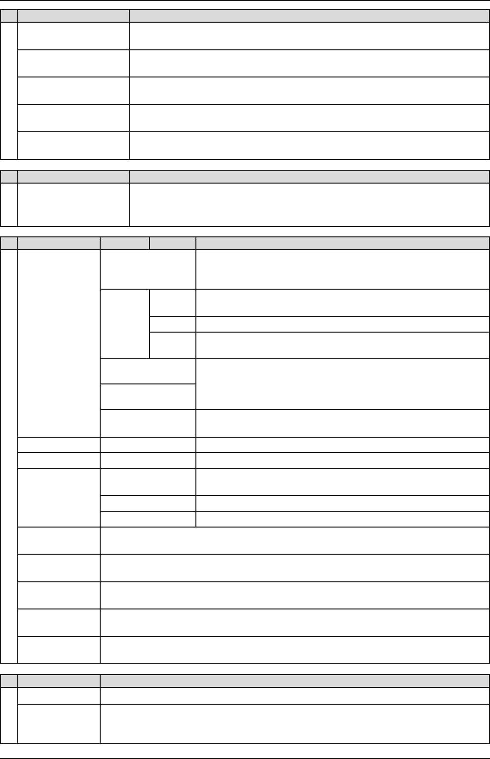
IF Level 1 Description
Devicenet
Node Address
Selection of the Devicenet node address in the range 0...63 via direct input
Baud Rate
Selection of the data communication speed with 125 kbps, 250 kbps or 500 kbps (1 kbps
= 1024 Baud) as bus baud rate. Selection „AUTO“ will let the slave device wait for the
master to initiate bus trafc in order to detect the baud rate on the bus automatically