
User manual


Table Of Contents
- 06230304_MA-PSI9000-2U-TFT-DE
- 1. Allgemeines
- 1.1 Zu diesem Dokument
- 1.2 Gewährleistung und Garantie
- 1.3 Haftungsbeschränkungen
- 1.4 Entsorgung des Gerätes
- 1.5 Produktschlüssel
- 1.6 Bestimmungsgemäße Verwendung
- 1.7 Sicherheit
- 1.8 Technische Daten
- 1.9 Aufbau und Funktion
- 1.9.1 Allgemeine Beschreibung
- 1.9.2 Blockdiagramm
- 1.9.3 Lieferumfang
- 1.9.4 Zubehör
- 1.9.5 Optionen
- 1.9.6 Die Bedieneinheit (HMI)
- 1.9.7 USB-Port (Rückseite)
- 1.9.8 Steckplatz für Schnittstellenmodule
- 1.9.9 Analogschnittstelle
- 1.9.10 Share-Bus-Anschluß
- 1.9.11 Sense-Anschluß (Fernfühlung)
- 1.9.12 Master-Slave-Bus
- 1.9.13 GPIB-Port (optional)
- 2. Installation & Inbetriebnahme
- 2.1 Transport und Lagerung
- 2.2 Auspacken und Sichtkontrolle
- 2.3 Installation
- 2.3.1 Sicherheitsmaßnahmen vor Installation und Gebrauch
- 2.3.2 Vorbereitung
- 2.3.3 Aufstellung des Gerätes
- 2.3.4 Anschließen an das Stromnetz (AC)
- 2.3.5 Anschließen von DC-Lasten
- 2.3.6 Erdung des DC-Ausgangs
- 2.3.7 Anschließen der Fernfühlung
- 2.3.8 Installation eines AnyBus-Schnittstellenmoduls
- 2.3.9 Anschließen der analogen Schnittstelle
- 2.3.10 Anschließen des „Share-Bus“
- 2.3.11 Anschließen des USB-Ports (Rückseite)
- 2.3.12 Erstinbetriebnahme
- 2.3.13 Erneute Inbetriebnahme nach Firmwareupdates bzw. längerer Nichtbenutzung
- 3. Bedienung und Verwendung
- 3.1 Personenschutz
- 3.2 Regelungsarten
- 3.3 Alarmzustände
- 3.4 Manuelle Bedienung
- 3.5 Fernsteuerung
- 3.6 Alarme und Überwachung
- 3.7 Bedieneinheit (HMI) sperren
- 3.8 Nutzerprofile laden und speichern
- 3.9 Der Funktionsgenerator
- 3.9.1 Einleitung
- 3.9.2 Allgemeines
- 3.9.3 Arbeitsweise
- 3.9.4 Manuelle Bedienung
- 3.9.5 Sinus-Funktion
- 3.9.6 Dreieck-Funktion
- 3.9.7 Rechteck-Funktion
- 3.9.8 Trapez-Funktion
- 3.9.9 DIN 40839-Funktion
- 3.9.10 Arbiträr-Funktion
- 3.9.11 Rampen-Funktion
- 3.9.12 UI- und IU-Tabellenfunktion (XY-Tabelle)
- 3.9.13 PV-Tabellenfunktion (Photovoltaik)
- 3.9.14 FC-Tabellenfunktion (Brennstoffzelle)
- 3.9.15 Fernsteuerung des Funktionsgenerators
- 3.10 Weitere Anwendungen
- 4. Instandhaltung & Wartung
- 5. Zubehör und Optionen
- 6. Service & Support
- 1. Allgemeines
- 06230304_MA-PSI9000-2U-TFT-EN
- 1. General
- 1.1 About this document
- 1.2 Warranty
- 1.3 Limitation of liability
- 1.4 Disposal of equipment
- 1.5 Product key
- 1.6 Intended usage
- 1.7 Safety
- 1.8 Technical Data
- 1.9 Construction and function
- 1.9.1 General description
- 1.9.2 Block diagram
- 1.9.3 Scope of delivery
- 1.9.4 Accessories
- 1.9.5 Options
- 1.9.6 The control panel (HMI)
- 1.9.7 USB port (rear side)
- 1.9.8 Interface module slot
- 1.9.9 Analog interface
- 1.9.10 Share Bus-Connection
- 1.9.11 Sense connector (remote sensing)
- 1.9.12 Master-Slave bus
- 1.9.13 GPIB port (optional)
- 2. Installation & commissioning
- 2.1 Transport and storage
- 2.2 Unpacking and visual check
- 2.3 Installation
- 2.3.1 Safety procedures before installation and use
- 2.3.2 Preparation
- 2.3.3 Installing the device
- 2.3.4 Connection to AC supply
- 2.3.5 Connection to DC loads
- 2.3.6 Grounding of the DC output
- 2.3.7 Connection of remote sensing
- 2.3.8 Installation of an AnyBus interface module
- 2.3.9 Connecting the analog interface
- 2.3.10 Connecting the “Share” bus
- 2.3.11 Connecting the USB port (rear side)
- 2.3.12 Initial commission
- 2.3.13 Commission after a firmware update or a long period of non-use
- 3. Operation and application
- 3.1 Personal safety
- 3.2 Operating modes
- 3.3 Alarm conditions
- 3.4 Manual operation
- 3.5 Remote control
- 3.6 Alarms and monitoring
- 3.7 Control panel (HMI) lock
- 3.8 Loading and saving a user profile
- 3.9 The function generator
- 3.9.1 Introduction
- 3.9.2 General
- 3.9.3 Method of operation
- 3.9.4 Manual operation
- 3.9.5 Sine wave function
- 3.9.6 Triangular function
- 3.9.7 Rectangular function
- 3.9.8 Trapezoidal function
- 3.9.9 DIN 40839 function
- 3.9.10 Arbitrary function
- 3.9.11 Ramp Function
- 3.9.12 UI and IU table functions (XY table)
- 3.9.13 PV table function (photovoltaics)
- 3.9.14 FC table function (fuel cell)
- 3.9.15 Remote control of the function generator
- 3.10 Other applications
- 4. Service and maintenance
- 5. Accessories and options
- 6. Service & Support
- 1. General
Page 82
PSI 9000 2U Series
www.elektroautomatik.de
ea1974@elektroautomatik.de
EA Elektro-Automatik GmbH
Helmholtzstr. 31-33 • 41747 Viersen
Germany
Fon: +49 2162 / 3785-0
Fax: +49 2162 / 16230
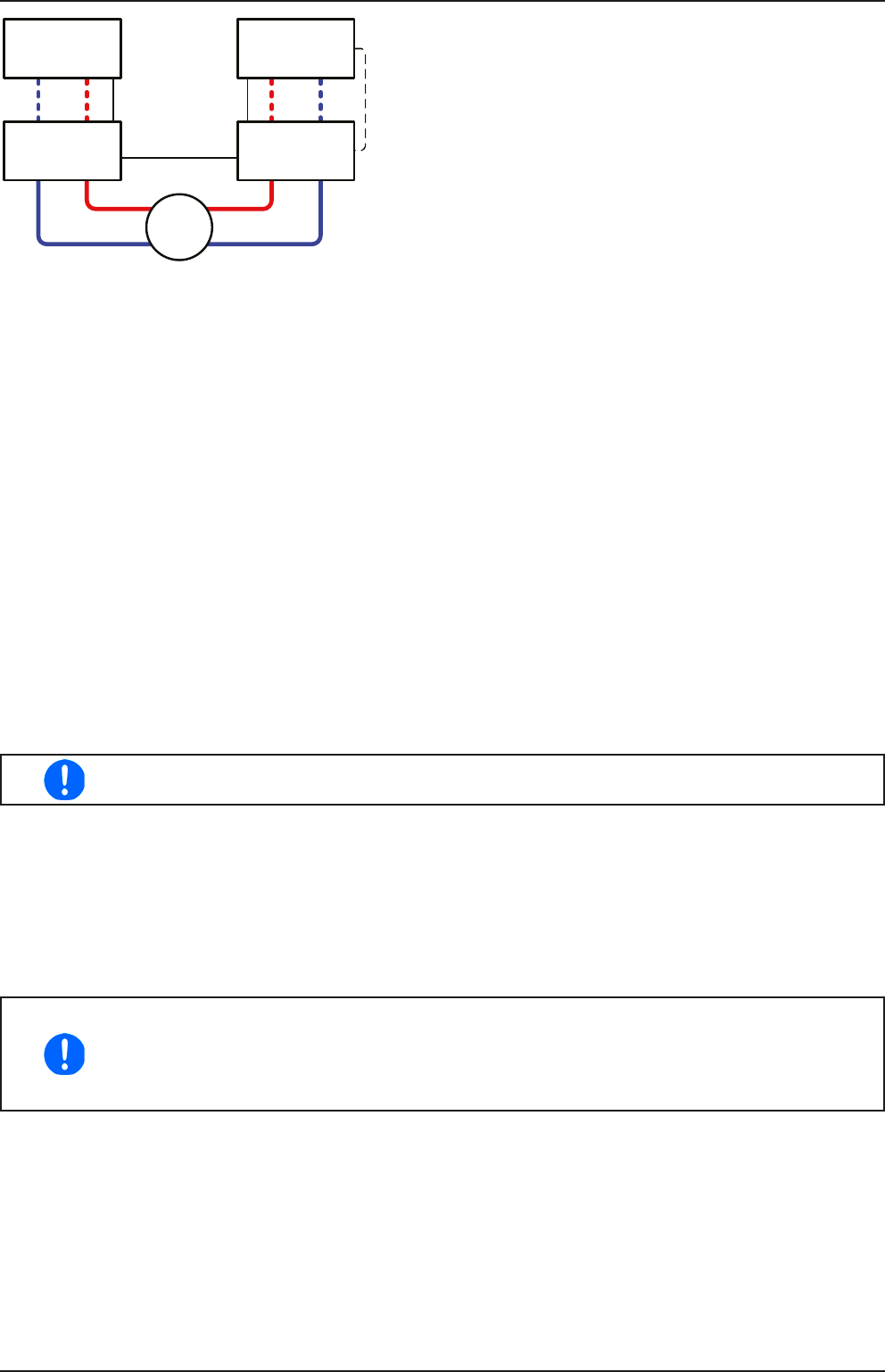
E.U.T
E-LOAD 1 PSU 1
PSU nE-LOAD n
Master-Slave
SB
Share-Bus
SB
Conguration C:
Multiple e-loads and Multiple power supplies, plus 1 test
object (E.U.T), for raising the total performance.
The combination of load units and power supply units each
create a block, a system with certain power. Here it is also
necessary to match the nominal values of the two systems,
i.e an 80 V DC input of the loads to a max. 80 V DC output
of the power supplies.
The max. number of 10 units cannot be exceeded. Regarding
the Share bus connection, all e-load units have to be slaves,
while one of the PSUs has to be set as master. In case the
digital master-slave bus, where featured, is also wired, one
load unit will be dened as master for the MS system of load,
but still has to be slave on the Share bus, which is activated
with parameter “PSI/ELR system” in the setup menu.
3.10.3.3 Settings on the devices
Regarding the general 2QO operation where the Share bus connection is sufcient, no extra setup is required on
the load unit(s). On any of the power supplies, but preferably PSU 1, you need to activate master-slave mode and
set it to MASTER, unless it is already the master unit of a master-slave system over digital MS bus. Refer to the
documentation of the power supply for further information. Also see 3.4.3.1.
For safety of the connected E.U.T / D.U.T and to prevent damage, we recommend to adjust supervision thresholds
like OVP, OCP or OPP on all units to the desired levels, which will then switch off the DC output resp. the DC input
in case of excess.
3.10.3.4 Application example
Charging and discharging a battery with 24 V/400 Ah, using conguration A from above.
• Power supply PSI 9080-120 2U with: I
Set
= 50 A, P
Set
= 5000 W
• Electronic load ELR 9080-170 set to: I
Set
= max. discharging current of the battery (eg. 100 A), P
Set
= 3500 W,
U
Set
= 24 V and UVD = 20 V or any other minimum value to which the battery shall be discharged to
• Assumption: battery has a voltage of 26 V at test start
• DC input(s) and DC output(s) of all units switched off
In this combination of devices it is recommended to always switch on the DC output of the
source rst and then the DC input of the sink.
1. Discharge of the battery to 24 V
Setup: Voltage on the power supply set to 24 V, DC output of power supply and DC input of load activated
Reaction: the e-load will load the battery with a maximum current of 100 A in order to discharge it to 24 V. The
power supply delivers no current at this moment, because the battery voltage is still higher than what is adjusted on
the power supply. The load will gradually reduce the input current in order to maintain the battery voltage at 24 V.
Once the battery voltage has reached 24 V with a discharge current of approx. 0 A, the voltage will be maintained
at this level by charging from the power supply.
The power supply determines the voltage setting of the load via the Share bus. In order to avoid
deep discharge of the battery due to accidentally setting the voltage on the power to a very low
value, it is recommended to congure the undervoltage detection feature (UVD) of the load, so
it will switch off the DC input when reaching minimum allowed discharge voltage. The settings
of the load, as given via the Share bus, can’t be read from the load’s display.
2. Charging the battery to 27 V
Setup: Voltage on the power supply set to 27 V
Reaction: the power supply will charge the battery with a maximum current of 50 A, which will gradually reduce
with increasing voltage as a reaction to the changing internal resistance of the battery. The load absorbs no current
at this charging phase, because it is controlled via the Share bus and set to a certain voltage, which is still higher
than the actual battery voltage and the actual output voltage of the power supply. When reaching 27 V, the power
supply will deliver only the current needed to maintain battery voltage.