
User manual


Table Of Contents
- 06230304_MA-PSI9000-2U-TFT-DE
- 1. Allgemeines
- 1.1 Zu diesem Dokument
- 1.2 Gewährleistung und Garantie
- 1.3 Haftungsbeschränkungen
- 1.4 Entsorgung des Gerätes
- 1.5 Produktschlüssel
- 1.6 Bestimmungsgemäße Verwendung
- 1.7 Sicherheit
- 1.8 Technische Daten
- 1.9 Aufbau und Funktion
- 1.9.1 Allgemeine Beschreibung
- 1.9.2 Blockdiagramm
- 1.9.3 Lieferumfang
- 1.9.4 Zubehör
- 1.9.5 Optionen
- 1.9.6 Die Bedieneinheit (HMI)
- 1.9.7 USB-Port (Rückseite)
- 1.9.8 Steckplatz für Schnittstellenmodule
- 1.9.9 Analogschnittstelle
- 1.9.10 Share-Bus-Anschluß
- 1.9.11 Sense-Anschluß (Fernfühlung)
- 1.9.12 Master-Slave-Bus
- 1.9.13 GPIB-Port (optional)
- 2. Installation & Inbetriebnahme
- 2.1 Transport und Lagerung
- 2.2 Auspacken und Sichtkontrolle
- 2.3 Installation
- 2.3.1 Sicherheitsmaßnahmen vor Installation und Gebrauch
- 2.3.2 Vorbereitung
- 2.3.3 Aufstellung des Gerätes
- 2.3.4 Anschließen an das Stromnetz (AC)
- 2.3.5 Anschließen von DC-Lasten
- 2.3.6 Erdung des DC-Ausgangs
- 2.3.7 Anschließen der Fernfühlung
- 2.3.8 Installation eines AnyBus-Schnittstellenmoduls
- 2.3.9 Anschließen der analogen Schnittstelle
- 2.3.10 Anschließen des „Share-Bus“
- 2.3.11 Anschließen des USB-Ports (Rückseite)
- 2.3.12 Erstinbetriebnahme
- 2.3.13 Erneute Inbetriebnahme nach Firmwareupdates bzw. längerer Nichtbenutzung
- 3. Bedienung und Verwendung
- 3.1 Personenschutz
- 3.2 Regelungsarten
- 3.3 Alarmzustände
- 3.4 Manuelle Bedienung
- 3.5 Fernsteuerung
- 3.6 Alarme und Überwachung
- 3.7 Bedieneinheit (HMI) sperren
- 3.8 Nutzerprofile laden und speichern
- 3.9 Der Funktionsgenerator
- 3.9.1 Einleitung
- 3.9.2 Allgemeines
- 3.9.3 Arbeitsweise
- 3.9.4 Manuelle Bedienung
- 3.9.5 Sinus-Funktion
- 3.9.6 Dreieck-Funktion
- 3.9.7 Rechteck-Funktion
- 3.9.8 Trapez-Funktion
- 3.9.9 DIN 40839-Funktion
- 3.9.10 Arbiträr-Funktion
- 3.9.11 Rampen-Funktion
- 3.9.12 UI- und IU-Tabellenfunktion (XY-Tabelle)
- 3.9.13 PV-Tabellenfunktion (Photovoltaik)
- 3.9.14 FC-Tabellenfunktion (Brennstoffzelle)
- 3.9.15 Fernsteuerung des Funktionsgenerators
- 3.10 Weitere Anwendungen
- 4. Instandhaltung & Wartung
- 5. Zubehör und Optionen
- 6. Service & Support
- 1. Allgemeines
- 06230304_MA-PSI9000-2U-TFT-EN
- 1. General
- 1.1 About this document
- 1.2 Warranty
- 1.3 Limitation of liability
- 1.4 Disposal of equipment
- 1.5 Product key
- 1.6 Intended usage
- 1.7 Safety
- 1.8 Technical Data
- 1.9 Construction and function
- 1.9.1 General description
- 1.9.2 Block diagram
- 1.9.3 Scope of delivery
- 1.9.4 Accessories
- 1.9.5 Options
- 1.9.6 The control panel (HMI)
- 1.9.7 USB port (rear side)
- 1.9.8 Interface module slot
- 1.9.9 Analog interface
- 1.9.10 Share Bus-Connection
- 1.9.11 Sense connector (remote sensing)
- 1.9.12 Master-Slave bus
- 1.9.13 GPIB port (optional)
- 2. Installation & commissioning
- 2.1 Transport and storage
- 2.2 Unpacking and visual check
- 2.3 Installation
- 2.3.1 Safety procedures before installation and use
- 2.3.2 Preparation
- 2.3.3 Installing the device
- 2.3.4 Connection to AC supply
- 2.3.5 Connection to DC loads
- 2.3.6 Grounding of the DC output
- 2.3.7 Connection of remote sensing
- 2.3.8 Installation of an AnyBus interface module
- 2.3.9 Connecting the analog interface
- 2.3.10 Connecting the “Share” bus
- 2.3.11 Connecting the USB port (rear side)
- 2.3.12 Initial commission
- 2.3.13 Commission after a firmware update or a long period of non-use
- 3. Operation and application
- 3.1 Personal safety
- 3.2 Operating modes
- 3.3 Alarm conditions
- 3.4 Manual operation
- 3.5 Remote control
- 3.6 Alarms and monitoring
- 3.7 Control panel (HMI) lock
- 3.8 Loading and saving a user profile
- 3.9 The function generator
- 3.9.1 Introduction
- 3.9.2 General
- 3.9.3 Method of operation
- 3.9.4 Manual operation
- 3.9.5 Sine wave function
- 3.9.6 Triangular function
- 3.9.7 Rectangular function
- 3.9.8 Trapezoidal function
- 3.9.9 DIN 40839 function
- 3.9.10 Arbitrary function
- 3.9.11 Ramp Function
- 3.9.12 UI and IU table functions (XY table)
- 3.9.13 PV table function (photovoltaics)
- 3.9.14 FC table function (fuel cell)
- 3.9.15 Remote control of the function generator
- 3.10 Other applications
- 4. Service and maintenance
- 5. Accessories and options
- 6. Service & Support
- 1. General
Page 56
PSI 9000 2U Series
www.elektroautomatik.de
ea1974@elektroautomatik.de
EA Elektro-Automatik GmbH
Helmholtzstr. 31-33 • 41747 Viersen
Germany
Fon: +49 2162 / 3785-0
Fax: +49 2162 / 16230
3.5.4.2 Acknowledging device alarms
Device alarms (see 3.6.2) are always indicated in the front display and some of them are also reported as signal on
the analog interface socket (see 3.5.4.3), for example the overvoltage alarm (OV), which is considered as critical.
In case of a device alarm occurring during remote control via analog interface, the DC output will be switched off
the same way as in manual control. While alarms OT and OV can be monitored via the corresponding pins of the
interface, other alarms like power fail (PF) can’t. Those could only be monitored and detected via the actual values
of voltage and current being all zero contrary to the set values.
All device alarms (OT, OV, PF, OCP and OPP) have to be acknowledged, either by the user of the device or by the
controlling unit. Also see „3.6.2. Device alarm and event handling“. Acknowledgement is done with pin REM-SB
switching the DC output off and on again, means a HIGH-LOW-HIGH edge (min. 50ms for LOW).
3.5.4.3 Analog interface specication
Pin Name Type* Description Levels Electrical properties
1 VSEL AI Set voltage value
0…10 V or. 0...5 V correspond
to 0..100% of U
Nom
Accuracy < 0.2% *****
Input impedance R
i
>40 k...100 k
2 CSEL AI Set current value
0…10 V or. 0...5 V correspond
to 0..100% of I
Nom
3 VREF AO Reference voltage 10 V or 5 V
Tolerance < 0.2% at I
max
= +5 mA
Short-circuit-proof against AGND
4 DGND POT
Ground for all digi-
tal signals
For control and status signals.
5 REMOTE DI
Switching internal /
remote control
Remote = LOW, U
Low
<1 V
Internal = HIGH, U
High
>4 V
Internal = Open
Voltage range = 0…30 V
I
Max
= -1 mA bei 5 V
U
LOW to HIGH typ.
= 3 V
Rec’d sender: Open collector against DGND
6 OT DO
Overheating or
power fail*** alarm
Alarm OT= HIGH, U
High
> 4 V
No Alarm OT= LOW, U
Low
<1 V
Quasi open collector with pull-up against Vcc **
With 5 V on the pin max. ow +1 mA
I
Max
= -10 mA at U
CE
= 0,3 V
U
Max
= 30 V
Short-circuit-proof against DGND
7 - - - - -
8 PSEL AI Set power value
0…10 V or. 0...5 V correspond
to 0..100% von P
Nom
Accuracy < 0.2% *****
Input impedance R
i
>40 k...100 k
9 VMON AO Actual voltage
0…10 V or. 0...5 V correspond
to 0..100% von U
Nom
Accuracy < 0.2% at I
Max
= +2 mA
Short-circuit-proof against AGND
10 CMON AO Actual current
0…10 V or. 0...5 V correspond
to 0..100% von I
Nom
11 AGND POT
Ground for all
analog signals
For -SEL, -MON, VREF Signals
12 - - - - -
13 REM-SB DI
DC output OFF
(DC output ON)
(ACK alarms ****)
Off = LOW, U
Low
<1 V
On= HIGH, U
High
>4 V
On = Open
Voltage range = 0…30 V
I
Max
= +1 mA at 5 V
Rec’d sender: Open collector against DGND
14 OVP DO Overvoltage alarm
Alarm OV = HIGH, U
High
> 4 V
No alarm OV = LOW, U
Low
<1 V
Quasi open collector with pull-up against Vcc **
With 5 V on the pin max. ow +1 mA
I
Max
= -10 mA at U
CE
= 0,3 V, U
Max
= 30 V
Short-circuit-proof against DGND
15 CV DO
Constant voltage
regulation active
CV = LOW, U
Low
<1 V
CC/CP/CR = HIGH, U
High
>4 V
* AI = Analog Input, AO = Analog Output, DI = Digital Input, DO = Digital Output, POT = Potential ** Internal Vcc approx. 10 V
*** Mains blackout, mains over- or undervoltage or PFC error **** Only during remote control ***** The error of a set value input adds to the general error
of the related value on the DC output of the device
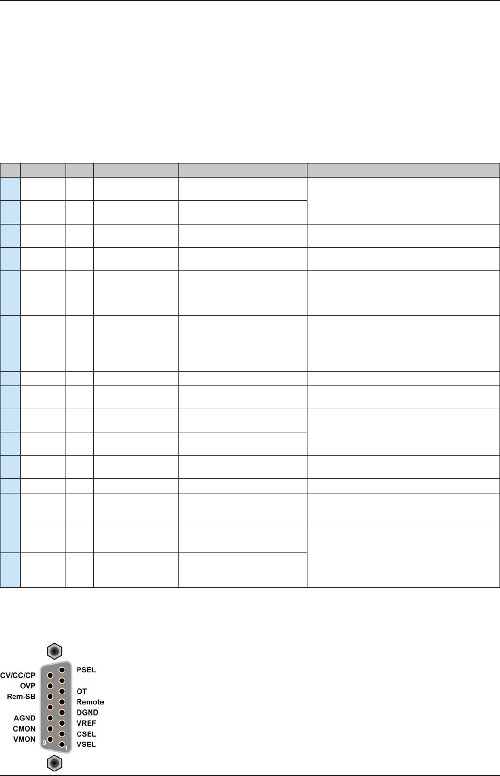
3.5.4.4 Overview of the Sub-D Socket