
User manual


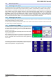


Table Of Contents
- 06230304_MA-PSI9000-2U-TFT-DE
- 1. Allgemeines
- 1.1 Zu diesem Dokument
- 1.2 Gewährleistung und Garantie
- 1.3 Haftungsbeschränkungen
- 1.4 Entsorgung des Gerätes
- 1.5 Produktschlüssel
- 1.6 Bestimmungsgemäße Verwendung
- 1.7 Sicherheit
- 1.8 Technische Daten
- 1.9 Aufbau und Funktion
- 1.9.1 Allgemeine Beschreibung
- 1.9.2 Blockdiagramm
- 1.9.3 Lieferumfang
- 1.9.4 Zubehör
- 1.9.5 Optionen
- 1.9.6 Die Bedieneinheit (HMI)
- 1.9.7 USB-Port (Rückseite)
- 1.9.8 Steckplatz für Schnittstellenmodule
- 1.9.9 Analogschnittstelle
- 1.9.10 Share-Bus-Anschluß
- 1.9.11 Sense-Anschluß (Fernfühlung)
- 1.9.12 Master-Slave-Bus
- 1.9.13 GPIB-Port (optional)
- 2. Installation & Inbetriebnahme
- 2.1 Transport und Lagerung
- 2.2 Auspacken und Sichtkontrolle
- 2.3 Installation
- 2.3.1 Sicherheitsmaßnahmen vor Installation und Gebrauch
- 2.3.2 Vorbereitung
- 2.3.3 Aufstellung des Gerätes
- 2.3.4 Anschließen an das Stromnetz (AC)
- 2.3.5 Anschließen von DC-Lasten
- 2.3.6 Erdung des DC-Ausgangs
- 2.3.7 Anschließen der Fernfühlung
- 2.3.8 Installation eines AnyBus-Schnittstellenmoduls
- 2.3.9 Anschließen der analogen Schnittstelle
- 2.3.10 Anschließen des „Share-Bus“
- 2.3.11 Anschließen des USB-Ports (Rückseite)
- 2.3.12 Erstinbetriebnahme
- 2.3.13 Erneute Inbetriebnahme nach Firmwareupdates bzw. längerer Nichtbenutzung
- 3. Bedienung und Verwendung
- 3.1 Personenschutz
- 3.2 Regelungsarten
- 3.3 Alarmzustände
- 3.4 Manuelle Bedienung
- 3.5 Fernsteuerung
- 3.6 Alarme und Überwachung
- 3.7 Bedieneinheit (HMI) sperren
- 3.8 Nutzerprofile laden und speichern
- 3.9 Der Funktionsgenerator
- 3.9.1 Einleitung
- 3.9.2 Allgemeines
- 3.9.3 Arbeitsweise
- 3.9.4 Manuelle Bedienung
- 3.9.5 Sinus-Funktion
- 3.9.6 Dreieck-Funktion
- 3.9.7 Rechteck-Funktion
- 3.9.8 Trapez-Funktion
- 3.9.9 DIN 40839-Funktion
- 3.9.10 Arbiträr-Funktion
- 3.9.11 Rampen-Funktion
- 3.9.12 UI- und IU-Tabellenfunktion (XY-Tabelle)
- 3.9.13 PV-Tabellenfunktion (Photovoltaik)
- 3.9.14 FC-Tabellenfunktion (Brennstoffzelle)
- 3.9.15 Fernsteuerung des Funktionsgenerators
- 3.10 Weitere Anwendungen
- 4. Instandhaltung & Wartung
- 5. Zubehör und Optionen
- 6. Service & Support
- 1. Allgemeines
- 06230304_MA-PSI9000-2U-TFT-EN
- 1. General
- 1.1 About this document
- 1.2 Warranty
- 1.3 Limitation of liability
- 1.4 Disposal of equipment
- 1.5 Product key
- 1.6 Intended usage
- 1.7 Safety
- 1.8 Technical Data
- 1.9 Construction and function
- 1.9.1 General description
- 1.9.2 Block diagram
- 1.9.3 Scope of delivery
- 1.9.4 Accessories
- 1.9.5 Options
- 1.9.6 The control panel (HMI)
- 1.9.7 USB port (rear side)
- 1.9.8 Interface module slot
- 1.9.9 Analog interface
- 1.9.10 Share Bus-Connection
- 1.9.11 Sense connector (remote sensing)
- 1.9.12 Master-Slave bus
- 1.9.13 GPIB port (optional)
- 2. Installation & commissioning
- 2.1 Transport and storage
- 2.2 Unpacking and visual check
- 2.3 Installation
- 2.3.1 Safety procedures before installation and use
- 2.3.2 Preparation
- 2.3.3 Installing the device
- 2.3.4 Connection to AC supply
- 2.3.5 Connection to DC loads
- 2.3.6 Grounding of the DC output
- 2.3.7 Connection of remote sensing
- 2.3.8 Installation of an AnyBus interface module
- 2.3.9 Connecting the analog interface
- 2.3.10 Connecting the “Share” bus
- 2.3.11 Connecting the USB port (rear side)
- 2.3.12 Initial commission
- 2.3.13 Commission after a firmware update or a long period of non-use
- 3. Operation and application
- 3.1 Personal safety
- 3.2 Operating modes
- 3.3 Alarm conditions
- 3.4 Manual operation
- 3.5 Remote control
- 3.6 Alarms and monitoring
- 3.7 Control panel (HMI) lock
- 3.8 Loading and saving a user profile
- 3.9 The function generator
- 3.9.1 Introduction
- 3.9.2 General
- 3.9.3 Method of operation
- 3.9.4 Manual operation
- 3.9.5 Sine wave function
- 3.9.6 Triangular function
- 3.9.7 Rectangular function
- 3.9.8 Trapezoidal function
- 3.9.9 DIN 40839 function
- 3.9.10 Arbitrary function
- 3.9.11 Ramp Function
- 3.9.12 UI and IU table functions (XY table)
- 3.9.13 PV table function (photovoltaics)
- 3.9.14 FC table function (fuel cell)
- 3.9.15 Remote control of the function generator
- 3.10 Other applications
- 4. Service and maintenance
- 5. Accessories and options
- 6. Service & Support
- 1. General

Page 39
EA Elektro-Automatik GmbH
Helmholtzstr. 31-33 • 41747 Viersen
Germany
Fon: +49 2162 / 3785-0
Fax: +49 2162 / 16230
www.elektroautomatik.de
ea1974@elektroautomatik.de
PSI 9000 2U Series
2.3.10 Connecting the “Share” bus
The “Share” bus connector on the back side is intended to balance the current of multiple units in parallel opera-
tion, especially when using the integrated function generator of the master unit. It is recommended to connect the
Share bus of any unit involved in parallel operation. Alternatively, it can be connected to a compatible electronic
load, like from series ELR 9000, in order to run a two-quadrants operation. For further information about this mode
of operation can be found in section „3.10.3. Two quadrant operation (2QO)“ .
For the connection of the share bus the following must be paid attention to:
• Connection is only permitted between compatible devices (see „1.9.10. Share Bus-Connection“
for details) and between a max. of 10 units
• If a two-quadrants operation system has to be set up where multiple power supplies are con-
nected to one electronic load unit or a group of electronic loads, all units should be connected
via Share bus. One power supply unit is then congured as Share bus master, similar to true
master-slave operation. The group of power supplies may use the master-slave bus for true
master-slave operation, the group of loads may not, because there must be only one master
unit on the Share bus.
2.3.11 Connecting the USB port (rear side)
In order to remotely control the device via this port, connect the device with a PC using the included USB cable
and switch the device on.
2.3.11.1 Driver installation (Windows)
On the initial connection with a PC the operating system will identify the device as new hardware and will install
the driver. The driver is a Communications Device Class (CDC) type and is usually integrated in current operating
systems such as Windows 7 or XP and is therefore not provided additionally. There are, however, versions such
as Windows 7 Embedded in which the class of driver is not installed or does not function.
On the included CD is a driver information le (*.inf) which can install the device as a virtual COM port (VCOM).
Following recognition, the USB equipment will rst be listed in the Windows Device Manager as “other hardware”
(Windows 7) and the driver may possibly not be fully installed. In this case take the following steps:
In Device Manager click with right mouse button on the not fully installed hardware. Select “Update driver”
1. Windows will ask if the driver should be automatically searched or whether it should be located and installed
manually. Select the latter (second choice in the dialogue window).
2. In the next dialogue window the driver source path will be determined. Click on “Search” and enter the folder
of the USB driver from the “Drivers & Tools” CD or the path to the downloaded and unpacked driver. Allow
Windows to install the driver. A message that the driver is not digitally signed can be submitted with “Ignore”.
2.3.11.2 Driver installation (Linux, MacOS)
We cannot provide drivers or installation instructions for these operating systems. Whether a suitable driver is
available is best carried out by searching the Internet.
2.3.11.3 Alternative drivers
In case the CDC drivers described above are not available on your system, or for some reason do not function
correctly, commercial suppliers can help. Search the Internet for suppliers using the keywords “cdc driver windows“
or “cdc driver linux“ or “cdc driver macos“.
2.3.12 Initial commission
For the rst start-up after installation of the device, the following procedures have to be executed:
• Conrm that the connection cables to be used are of a satisfactory cross section!
• Check if the factory settings of set values, safety and monitoring functions and communication are suitable for
your intended application of the device and adjust them if required, as described in the manual!
• In case of remote control via PC, read the additional documentation for interfaces and software!
• In case of remote control via the analog interface, read the section in this manual concerning analog interfaces!
2.3.13 Commission after a rmware update or a long period of non-use
In case of a rmware update, return of the equipment following repair or a location or conguration change, similar
measures should be taken to those of initial start up. Refer to „2.3.12. Initial commission“.
Only after successful checking of the device as listed may it be operated as usual.