
User manual


Table Of Contents
- 06230304_MA-PSI9000-2U-TFT-DE
- 1. Allgemeines
- 1.1 Zu diesem Dokument
- 1.2 Gewährleistung und Garantie
- 1.3 Haftungsbeschränkungen
- 1.4 Entsorgung des Gerätes
- 1.5 Produktschlüssel
- 1.6 Bestimmungsgemäße Verwendung
- 1.7 Sicherheit
- 1.8 Technische Daten
- 1.9 Aufbau und Funktion
- 1.9.1 Allgemeine Beschreibung
- 1.9.2 Blockdiagramm
- 1.9.3 Lieferumfang
- 1.9.4 Zubehör
- 1.9.5 Optionen
- 1.9.6 Die Bedieneinheit (HMI)
- 1.9.7 USB-Port (Rückseite)
- 1.9.8 Steckplatz für Schnittstellenmodule
- 1.9.9 Analogschnittstelle
- 1.9.10 Share-Bus-Anschluß
- 1.9.11 Sense-Anschluß (Fernfühlung)
- 1.9.12 Master-Slave-Bus
- 1.9.13 GPIB-Port (optional)
- 2. Installation & Inbetriebnahme
- 2.1 Transport und Lagerung
- 2.2 Auspacken und Sichtkontrolle
- 2.3 Installation
- 2.3.1 Sicherheitsmaßnahmen vor Installation und Gebrauch
- 2.3.2 Vorbereitung
- 2.3.3 Aufstellung des Gerätes
- 2.3.4 Anschließen an das Stromnetz (AC)
- 2.3.5 Anschließen von DC-Lasten
- 2.3.6 Erdung des DC-Ausgangs
- 2.3.7 Anschließen der Fernfühlung
- 2.3.8 Installation eines AnyBus-Schnittstellenmoduls
- 2.3.9 Anschließen der analogen Schnittstelle
- 2.3.10 Anschließen des „Share-Bus“
- 2.3.11 Anschließen des USB-Ports (Rückseite)
- 2.3.12 Erstinbetriebnahme
- 2.3.13 Erneute Inbetriebnahme nach Firmwareupdates bzw. längerer Nichtbenutzung
- 3. Bedienung und Verwendung
- 3.1 Personenschutz
- 3.2 Regelungsarten
- 3.3 Alarmzustände
- 3.4 Manuelle Bedienung
- 3.5 Fernsteuerung
- 3.6 Alarme und Überwachung
- 3.7 Bedieneinheit (HMI) sperren
- 3.8 Nutzerprofile laden und speichern
- 3.9 Der Funktionsgenerator
- 3.9.1 Einleitung
- 3.9.2 Allgemeines
- 3.9.3 Arbeitsweise
- 3.9.4 Manuelle Bedienung
- 3.9.5 Sinus-Funktion
- 3.9.6 Dreieck-Funktion
- 3.9.7 Rechteck-Funktion
- 3.9.8 Trapez-Funktion
- 3.9.9 DIN 40839-Funktion
- 3.9.10 Arbiträr-Funktion
- 3.9.11 Rampen-Funktion
- 3.9.12 UI- und IU-Tabellenfunktion (XY-Tabelle)
- 3.9.13 PV-Tabellenfunktion (Photovoltaik)
- 3.9.14 FC-Tabellenfunktion (Brennstoffzelle)
- 3.9.15 Fernsteuerung des Funktionsgenerators
- 3.10 Weitere Anwendungen
- 4. Instandhaltung & Wartung
- 5. Zubehör und Optionen
- 6. Service & Support
- 1. Allgemeines
- 06230304_MA-PSI9000-2U-TFT-EN
- 1. General
- 1.1 About this document
- 1.2 Warranty
- 1.3 Limitation of liability
- 1.4 Disposal of equipment
- 1.5 Product key
- 1.6 Intended usage
- 1.7 Safety
- 1.8 Technical Data
- 1.9 Construction and function
- 1.9.1 General description
- 1.9.2 Block diagram
- 1.9.3 Scope of delivery
- 1.9.4 Accessories
- 1.9.5 Options
- 1.9.6 The control panel (HMI)
- 1.9.7 USB port (rear side)
- 1.9.8 Interface module slot
- 1.9.9 Analog interface
- 1.9.10 Share Bus-Connection
- 1.9.11 Sense connector (remote sensing)
- 1.9.12 Master-Slave bus
- 1.9.13 GPIB port (optional)
- 2. Installation & commissioning
- 2.1 Transport and storage
- 2.2 Unpacking and visual check
- 2.3 Installation
- 2.3.1 Safety procedures before installation and use
- 2.3.2 Preparation
- 2.3.3 Installing the device
- 2.3.4 Connection to AC supply
- 2.3.5 Connection to DC loads
- 2.3.6 Grounding of the DC output
- 2.3.7 Connection of remote sensing
- 2.3.8 Installation of an AnyBus interface module
- 2.3.9 Connecting the analog interface
- 2.3.10 Connecting the “Share” bus
- 2.3.11 Connecting the USB port (rear side)
- 2.3.12 Initial commission
- 2.3.13 Commission after a firmware update or a long period of non-use
- 3. Operation and application
- 3.1 Personal safety
- 3.2 Operating modes
- 3.3 Alarm conditions
- 3.4 Manual operation
- 3.5 Remote control
- 3.6 Alarms and monitoring
- 3.7 Control panel (HMI) lock
- 3.8 Loading and saving a user profile
- 3.9 The function generator
- 3.9.1 Introduction
- 3.9.2 General
- 3.9.3 Method of operation
- 3.9.4 Manual operation
- 3.9.5 Sine wave function
- 3.9.6 Triangular function
- 3.9.7 Rectangular function
- 3.9.8 Trapezoidal function
- 3.9.9 DIN 40839 function
- 3.9.10 Arbitrary function
- 3.9.11 Ramp Function
- 3.9.12 UI and IU table functions (XY table)
- 3.9.13 PV table function (photovoltaics)
- 3.9.14 FC table function (fuel cell)
- 3.9.15 Remote control of the function generator
- 3.10 Other applications
- 4. Service and maintenance
- 5. Accessories and options
- 6. Service & Support
- 1. General
Page 30
PSI 9000 2U Series
www.elektroautomatik.de
ea1974@elektroautomatik.de
EA Elektro-Automatik GmbH
Helmholtzstr. 31-33 • 41747 Viersen
Germany
Fon: +49 2162 / 3785-0
Fax: +49 2162 / 16230
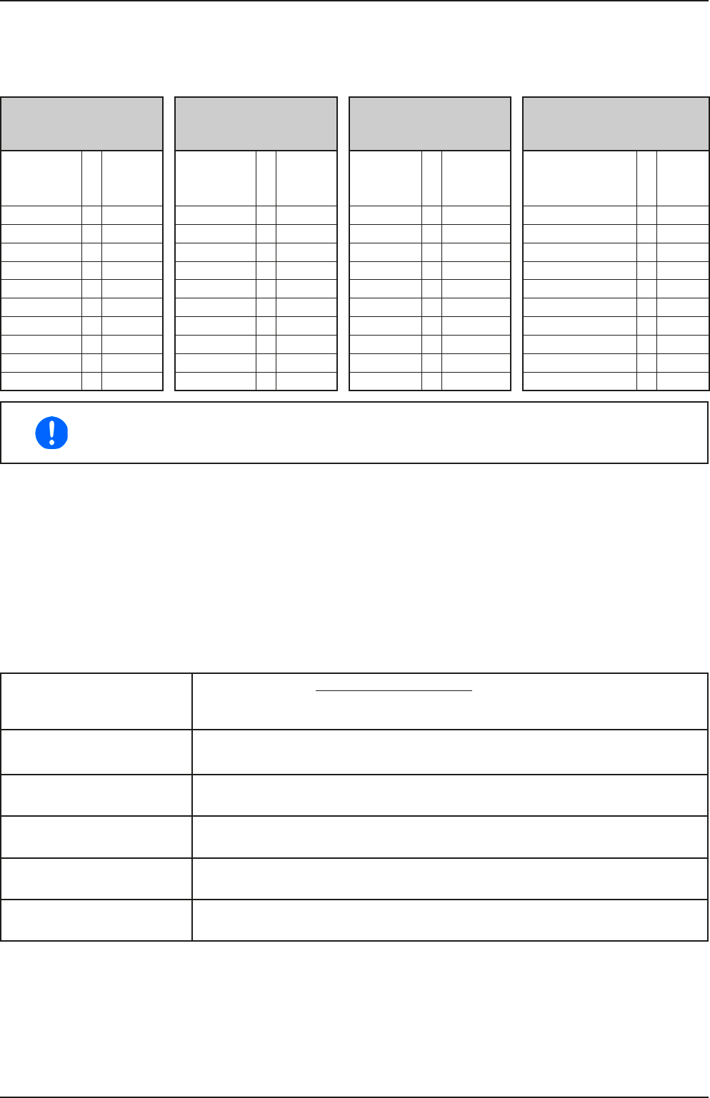
1.9.6.4 Resolution of the displayed values
In the display, set values can be adjusted in variable increments. The number of decimal places depends on the
device model and can have 3 or 5 digits. Related actual and set values always have the same number of digits.
Adjustable resolution and display formats for the touch panel display:
Voltage,
OVP, UVD, OVD,
U-min, U-max
Current,
OCP, UCD, OCD,
I-min, I-max
Power,
OPP, OPD,
P-max
Resistance,
R-max
Nominal
value
Digits
Min.
incre-
ment
Nominal
value
Digits
Min.
incre-
ment
Nominal
value
Digits
Min. in-
crement
Nominal
value
Digits
Min.
Incre-
ment
40 V / 80 V 4 0.01 V 4 A / 6 A 4 0.001 A 1 kW 4 0.001 kW 10 Ω / 20 Ω 5 0.01 Ω
200 V 5 0.01 V 10 A / 12 A 5 0.001 A 1.5 kW 4 0.001 kW 30 Ω / 40 Ω / 60 Ω 4 0.01 Ω
360 V 4 0.1 V 15 A / 20 A 5 0.001 A 3 kW 4 0.001 kW 120 Ω / 240 Ω 5 0.01 Ω
500 V 4 0.1 V 25 A 5 0.001 A 360 Ω / 400 Ω 4 0.1 Ω
750 V 4 0.1 V 30 A / 40 A 4 0.01 A 720 Ω / 750 Ω 4 0.1 Ω
50 A / 60 A 4 0.01 A 1080 Ω / 1500 Ω 5 0.1 Ω
120 A 5 0.01 A 1875 Ω 5 0.1 Ω
2500 Ω 5 0.1 Ω
3750 Ω 4 1 Ω
5625 Ω 4 1 Ω
In manual operation every set value can be set in the increments given above. In this case
the actual output values set by the device will lie within percentage tolerances as shown in the
technical data sheets. These will inuence the actual values.
1.9.6.5 USB-Port (Front side)
The frontal USB port, located to the right of the rotary knobs, is intended for the connection of standard USB ash
drives (ash drive). This can be used for:
• Loading or saving sequences for the arbitrary and loading tables for the UI-IU function generator
• Updating HMI rmware (new languages, functions)
USB ash drives must be FAT32 formatted and have a maximum capacity of 32GB. All supported les must
be held in a designated folder in the root path of the USB drive in order to be found. This folder must be named
HMI_FILES, such that a PC would recognise the path G:\HMI_FILES if the drive were to be assigned the letter
G. The control panel of the electronic load can read the following le types from a ash drive:
*.bin Firmware updates only for the control panel. The le name format is given like
96230058_FW-BE1_V204.bin, listed in short form as FW-BE1_V204.bin. Other
les won’t be recognised or listed.
wave_u<arbitrary>.csv
wave_i<arbitrary>.csv
Function generator arbitrary function for voltage (U) or current (I)
The name must begin with wave_u / wave_i, the rest is user dened.
iu<arbitrary>.csv IU table for the XY function generator.
The name must begin with iu, the rest can be user dened.
ui<arbitrary>.csv UI table for the XY function generator.
The name must begin with ui, the rest can be user dened.
pv<arbitrary>.csv PV (photovoltaics) table for XY the function generator.
The name must begin with pv, the rest can be user dened.
fc<arbitrary>.csv FC (fuel cell) table for the XY function generator.
The name must begin with fc, the rest can be user dened.