
User manual


Table Of Contents
- 06230304_MA-PSI9000-2U-TFT-DE
- 1. Allgemeines
- 1.1 Zu diesem Dokument
- 1.2 Gewährleistung und Garantie
- 1.3 Haftungsbeschränkungen
- 1.4 Entsorgung des Gerätes
- 1.5 Produktschlüssel
- 1.6 Bestimmungsgemäße Verwendung
- 1.7 Sicherheit
- 1.8 Technische Daten
- 1.9 Aufbau und Funktion
- 1.9.1 Allgemeine Beschreibung
- 1.9.2 Blockdiagramm
- 1.9.3 Lieferumfang
- 1.9.4 Zubehör
- 1.9.5 Optionen
- 1.9.6 Die Bedieneinheit (HMI)
- 1.9.7 USB-Port (Rückseite)
- 1.9.8 Steckplatz für Schnittstellenmodule
- 1.9.9 Analogschnittstelle
- 1.9.10 Share-Bus-Anschluß
- 1.9.11 Sense-Anschluß (Fernfühlung)
- 1.9.12 Master-Slave-Bus
- 1.9.13 GPIB-Port (optional)
- 2. Installation & Inbetriebnahme
- 2.1 Transport und Lagerung
- 2.2 Auspacken und Sichtkontrolle
- 2.3 Installation
- 2.3.1 Sicherheitsmaßnahmen vor Installation und Gebrauch
- 2.3.2 Vorbereitung
- 2.3.3 Aufstellung des Gerätes
- 2.3.4 Anschließen an das Stromnetz (AC)
- 2.3.5 Anschließen von DC-Lasten
- 2.3.6 Erdung des DC-Ausgangs
- 2.3.7 Anschließen der Fernfühlung
- 2.3.8 Installation eines AnyBus-Schnittstellenmoduls
- 2.3.9 Anschließen der analogen Schnittstelle
- 2.3.10 Anschließen des „Share-Bus“
- 2.3.11 Anschließen des USB-Ports (Rückseite)
- 2.3.12 Erstinbetriebnahme
- 2.3.13 Erneute Inbetriebnahme nach Firmwareupdates bzw. längerer Nichtbenutzung
- 3. Bedienung und Verwendung
- 3.1 Personenschutz
- 3.2 Regelungsarten
- 3.3 Alarmzustände
- 3.4 Manuelle Bedienung
- 3.5 Fernsteuerung
- 3.6 Alarme und Überwachung
- 3.7 Bedieneinheit (HMI) sperren
- 3.8 Nutzerprofile laden und speichern
- 3.9 Der Funktionsgenerator
- 3.9.1 Einleitung
- 3.9.2 Allgemeines
- 3.9.3 Arbeitsweise
- 3.9.4 Manuelle Bedienung
- 3.9.5 Sinus-Funktion
- 3.9.6 Dreieck-Funktion
- 3.9.7 Rechteck-Funktion
- 3.9.8 Trapez-Funktion
- 3.9.9 DIN 40839-Funktion
- 3.9.10 Arbiträr-Funktion
- 3.9.11 Rampen-Funktion
- 3.9.12 UI- und IU-Tabellenfunktion (XY-Tabelle)
- 3.9.13 PV-Tabellenfunktion (Photovoltaik)
- 3.9.14 FC-Tabellenfunktion (Brennstoffzelle)
- 3.9.15 Fernsteuerung des Funktionsgenerators
- 3.10 Weitere Anwendungen
- 4. Instandhaltung & Wartung
- 5. Zubehör und Optionen
- 6. Service & Support
- 1. Allgemeines
- 06230304_MA-PSI9000-2U-TFT-EN
- 1. General
- 1.1 About this document
- 1.2 Warranty
- 1.3 Limitation of liability
- 1.4 Disposal of equipment
- 1.5 Product key
- 1.6 Intended usage
- 1.7 Safety
- 1.8 Technical Data
- 1.9 Construction and function
- 1.9.1 General description
- 1.9.2 Block diagram
- 1.9.3 Scope of delivery
- 1.9.4 Accessories
- 1.9.5 Options
- 1.9.6 The control panel (HMI)
- 1.9.7 USB port (rear side)
- 1.9.8 Interface module slot
- 1.9.9 Analog interface
- 1.9.10 Share Bus-Connection
- 1.9.11 Sense connector (remote sensing)
- 1.9.12 Master-Slave bus
- 1.9.13 GPIB port (optional)
- 2. Installation & commissioning
- 2.1 Transport and storage
- 2.2 Unpacking and visual check
- 2.3 Installation
- 2.3.1 Safety procedures before installation and use
- 2.3.2 Preparation
- 2.3.3 Installing the device
- 2.3.4 Connection to AC supply
- 2.3.5 Connection to DC loads
- 2.3.6 Grounding of the DC output
- 2.3.7 Connection of remote sensing
- 2.3.8 Installation of an AnyBus interface module
- 2.3.9 Connecting the analog interface
- 2.3.10 Connecting the “Share” bus
- 2.3.11 Connecting the USB port (rear side)
- 2.3.12 Initial commission
- 2.3.13 Commission after a firmware update or a long period of non-use
- 3. Operation and application
- 3.1 Personal safety
- 3.2 Operating modes
- 3.3 Alarm conditions
- 3.4 Manual operation
- 3.5 Remote control
- 3.6 Alarms and monitoring
- 3.7 Control panel (HMI) lock
- 3.8 Loading and saving a user profile
- 3.9 The function generator
- 3.9.1 Introduction
- 3.9.2 General
- 3.9.3 Method of operation
- 3.9.4 Manual operation
- 3.9.5 Sine wave function
- 3.9.6 Triangular function
- 3.9.7 Rectangular function
- 3.9.8 Trapezoidal function
- 3.9.9 DIN 40839 function
- 3.9.10 Arbitrary function
- 3.9.11 Ramp Function
- 3.9.12 UI and IU table functions (XY table)
- 3.9.13 PV table function (photovoltaics)
- 3.9.14 FC table function (fuel cell)
- 3.9.15 Remote control of the function generator
- 3.10 Other applications
- 4. Service and maintenance
- 5. Accessories and options
- 6. Service & Support
- 1. General
Page 79
EA Elektro-Automatik GmbH
Helmholtzstr. 31-33 • 41747 Viersen
Germany
Fon: +49 2162 / 3785-0
Fax: +49 2162 / 16230
www.elektroautomatik.de
ea1974@elektroautomatik.de
PSI 9000 2U Series
3.10.1.4 Operating the master-slave system
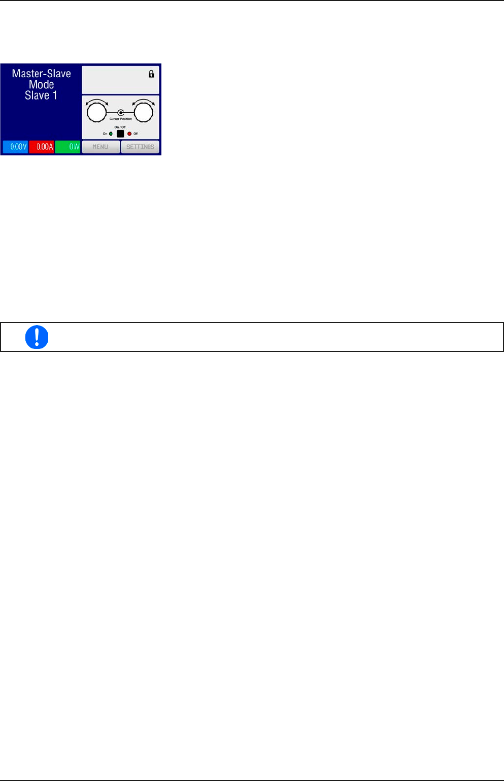
After successful conguration and initialisation of the master and slave units, these will show their status in the
displays. While the master merely shows “Master” in the status area, the slave(s) will continuously show like this,
as long they are in remote control by the master:
It means, aslong as a slave unit is in control by the master, it won’t display any
set or actual values, but it will show the DC output status and possible alarms.
The slaves can no longer be controlled manually or remotely, neither via the analog nor via digital interfaces. They
can, if needed, be monitored by reading actual values and status.
The display on the master unit changes after initialisation and all set values are reset. The master now displays
the set and actual values of the total system. Depending on the number of units, the total current and power will
multiply. The following applies:
• The master can be treated as a standalone unit
• The master shares the set values across the slaves and controls them
• The master is remotely controllable via the analog or digital interfaces
• All settings for the set values U,I and P (monitoring, settings limits etc.) will be adapted to the new total values
• All initialised slave will reset any limits (U
Min
, I
Max
etc.), supervision thresholds (OVP, OPP etc.) and event settings
(UCD, OVD etc.) to default values, so these don’t interfere the control by the master
In order to easily restore all these settings values to what was before activating MS operation, it
is recommended to make use of the user proles (see „3.8. Loading and saving a user prole“)
• If one or more slaves report an device alarm, this will be displayed on the master and must be acknowledged
there so that the slave(s) can continue operation. If the alarm had caused the DC output to be switched off then
this will be reinstated automatically by the master unit once the alarm has been acknowledged
• Loss of connection to any slave will result in shutdown of all DC outputs, as a safety measure, and the master
will report this situation in the display with a pop-up “Master-slave safety mode”. Then the MS system has to be
re-initialised, either with or without re-establishing connection to the disconnected unit(s) before
• All units, even the slaves, can be externally shut down on the DC outputs using the pin REM-SB of the analog
interface. This can be used as some kind of emergency off, where usually a contact (maker or breaker) is wired
to this pin on all unit in parallel
3.10.1.5 Alarms and other problem situations
Master-slave operation, due to the connection of multiple units and their interaction, can cause additional problem
situations which do not occur when operating individual units. For such occurrences the following regulations have
been dened:
• If the DC part of one or more slave units is switched off due to defect, overheating etc., the whole MS system
shuts down the power output and human interaction is required
• If one or more slave units are cut from AC supply (power switch, blackout, supply undervoltage) and come back
later, they’re not automatically initialised and included again in the MS system. Then the init has to be repeated.
• If the DC output of the master unit is switched off due to a defect or overheating, then the total master-slave
system can provide no output power and the DC outputs of all slaves are automatically switched off, too
• If the master unit is cut from AC supply (power switch, blackout) and comes back later, the unit will automati-
cally initialise the MS system again, nding and integrating all active slaves. In this case, MS can be restored
automatically.
• If accidently multiple or no units are dened as master the master-slave system cannot be initialised
In situations where one or multiple units generate a device alarm like OV, PF or OT following applies:
• Any alarm of a slave is indicated on the slave’s display and on the master’s display
• If multiple alarms happen simultaneously, the master only indicates the most recent one. In this case, the par-
ticular alarms can be read from the slave units displays or via digital interface during remote control or remote
supervision.