
User manual


Table Of Contents
- 06230304_MA-PSI9000-2U-TFT-DE
- 1. Allgemeines
- 1.1 Zu diesem Dokument
- 1.2 Gewährleistung und Garantie
- 1.3 Haftungsbeschränkungen
- 1.4 Entsorgung des Gerätes
- 1.5 Produktschlüssel
- 1.6 Bestimmungsgemäße Verwendung
- 1.7 Sicherheit
- 1.8 Technische Daten
- 1.9 Aufbau und Funktion
- 1.9.1 Allgemeine Beschreibung
- 1.9.2 Blockdiagramm
- 1.9.3 Lieferumfang
- 1.9.4 Zubehör
- 1.9.5 Optionen
- 1.9.6 Die Bedieneinheit (HMI)
- 1.9.7 USB-Port (Rückseite)
- 1.9.8 Steckplatz für Schnittstellenmodule
- 1.9.9 Analogschnittstelle
- 1.9.10 Share-Bus-Anschluß
- 1.9.11 Sense-Anschluß (Fernfühlung)
- 1.9.12 Master-Slave-Bus
- 1.9.13 GPIB-Port (optional)
- 2. Installation & Inbetriebnahme
- 2.1 Transport und Lagerung
- 2.2 Auspacken und Sichtkontrolle
- 2.3 Installation
- 2.3.1 Sicherheitsmaßnahmen vor Installation und Gebrauch
- 2.3.2 Vorbereitung
- 2.3.3 Aufstellung des Gerätes
- 2.3.4 Anschließen an das Stromnetz (AC)
- 2.3.5 Anschließen von DC-Lasten
- 2.3.6 Erdung des DC-Ausgangs
- 2.3.7 Anschließen der Fernfühlung
- 2.3.8 Installation eines AnyBus-Schnittstellenmoduls
- 2.3.9 Anschließen der analogen Schnittstelle
- 2.3.10 Anschließen des „Share-Bus“
- 2.3.11 Anschließen des USB-Ports (Rückseite)
- 2.3.12 Erstinbetriebnahme
- 2.3.13 Erneute Inbetriebnahme nach Firmwareupdates bzw. längerer Nichtbenutzung
- 3. Bedienung und Verwendung
- 3.1 Personenschutz
- 3.2 Regelungsarten
- 3.3 Alarmzustände
- 3.4 Manuelle Bedienung
- 3.5 Fernsteuerung
- 3.6 Alarme und Überwachung
- 3.7 Bedieneinheit (HMI) sperren
- 3.8 Nutzerprofile laden und speichern
- 3.9 Der Funktionsgenerator
- 3.9.1 Einleitung
- 3.9.2 Allgemeines
- 3.9.3 Arbeitsweise
- 3.9.4 Manuelle Bedienung
- 3.9.5 Sinus-Funktion
- 3.9.6 Dreieck-Funktion
- 3.9.7 Rechteck-Funktion
- 3.9.8 Trapez-Funktion
- 3.9.9 DIN 40839-Funktion
- 3.9.10 Arbiträr-Funktion
- 3.9.11 Rampen-Funktion
- 3.9.12 UI- und IU-Tabellenfunktion (XY-Tabelle)
- 3.9.13 PV-Tabellenfunktion (Photovoltaik)
- 3.9.14 FC-Tabellenfunktion (Brennstoffzelle)
- 3.9.15 Fernsteuerung des Funktionsgenerators
- 3.10 Weitere Anwendungen
- 4. Instandhaltung & Wartung
- 5. Zubehör und Optionen
- 6. Service & Support
- 1. Allgemeines
- 06230304_MA-PSI9000-2U-TFT-EN
- 1. General
- 1.1 About this document
- 1.2 Warranty
- 1.3 Limitation of liability
- 1.4 Disposal of equipment
- 1.5 Product key
- 1.6 Intended usage
- 1.7 Safety
- 1.8 Technical Data
- 1.9 Construction and function
- 1.9.1 General description
- 1.9.2 Block diagram
- 1.9.3 Scope of delivery
- 1.9.4 Accessories
- 1.9.5 Options
- 1.9.6 The control panel (HMI)
- 1.9.7 USB port (rear side)
- 1.9.8 Interface module slot
- 1.9.9 Analog interface
- 1.9.10 Share Bus-Connection
- 1.9.11 Sense connector (remote sensing)
- 1.9.12 Master-Slave bus
- 1.9.13 GPIB port (optional)
- 2. Installation & commissioning
- 2.1 Transport and storage
- 2.2 Unpacking and visual check
- 2.3 Installation
- 2.3.1 Safety procedures before installation and use
- 2.3.2 Preparation
- 2.3.3 Installing the device
- 2.3.4 Connection to AC supply
- 2.3.5 Connection to DC loads
- 2.3.6 Grounding of the DC output
- 2.3.7 Connection of remote sensing
- 2.3.8 Installation of an AnyBus interface module
- 2.3.9 Connecting the analog interface
- 2.3.10 Connecting the “Share” bus
- 2.3.11 Connecting the USB port (rear side)
- 2.3.12 Initial commission
- 2.3.13 Commission after a firmware update or a long period of non-use
- 3. Operation and application
- 3.1 Personal safety
- 3.2 Operating modes
- 3.3 Alarm conditions
- 3.4 Manual operation
- 3.5 Remote control
- 3.6 Alarms and monitoring
- 3.7 Control panel (HMI) lock
- 3.8 Loading and saving a user profile
- 3.9 The function generator
- 3.9.1 Introduction
- 3.9.2 General
- 3.9.3 Method of operation
- 3.9.4 Manual operation
- 3.9.5 Sine wave function
- 3.9.6 Triangular function
- 3.9.7 Rectangular function
- 3.9.8 Trapezoidal function
- 3.9.9 DIN 40839 function
- 3.9.10 Arbitrary function
- 3.9.11 Ramp Function
- 3.9.12 UI and IU table functions (XY table)
- 3.9.13 PV table function (photovoltaics)
- 3.9.14 FC table function (fuel cell)
- 3.9.15 Remote control of the function generator
- 3.10 Other applications
- 4. Service and maintenance
- 5. Accessories and options
- 6. Service & Support
- 1. General
Page 54
PSI 9000 2U Series
www.elektroautomatik.de
ea1974@elektroautomatik.de
EA Elektro-Automatik GmbH
Helmholtzstr. 31-33 • 41747 Viersen
Germany
Fon: +49 2162 / 3785-0
Fax: +49 2162 / 16230
3.5 Remote control
3.5.1 General
Remote control is possible via the built-in analog or USB port or via one of the optional interface modules (Any-
Bus CompactCom, only with standard models of PSI 9000 2U series) or via the GPIB port (only with option 3W
installed). Important here is that only the analog or one digital interface can be in control. It means that if, for ex-
ample, an attempt were to be made to switch to remote control via the digital interface whilst analog remote control
is active (Pin Remote = LOW) the device would report an error via the digital interface. In the opposite direction,
a switch-over via Pin Remote would be ignored. In both cases, however, status monitoring and reading of values
are always possible.
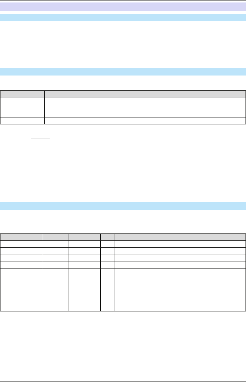
3.5.2 Control locations
Control locations are those locations from where the device is controlled. Essentially there are two: at the device
(manual operation) and outside (remote control). The following locations are dened:
Displayed location Description
- If neither of the other locations is displayed then manual control is active and access from
the analog and digital interfaces is allowed. This location is not explicitly displayed
Remote Remote control via any interface is active
Local Remote control is locked, only manual operation is allowed.
Remote control may be allowed or inhibited using the setting “Allow remote control” (see „3.4.3.1. Menu “General
Settings”“). In inhibited condition the status “Local” will be displayed top right. Activating the lock can be useful if
the device is remotely controlled by software or some electronic device, but it is required to make adjustments at
the device or deal with emergency, which would not be possible remotely.
Activating condition “Local” causes the following:
• If remote control via the digital interface is active (“Remote”). then remote control is immediately terminated and
must be reactivated at the PC once “Local” is no longer active.
• If remote control is via the analog interface is active (“Remote”) then remote operation is only interrupted until
remote control is allowed again, because pin “Remote” continues to signal “remote control = on”. Exception: if
the level of pin “Remote” is changed to HIGH during the “Local” phase.
3.5.3 Remote control via a digital interface
3.5.3.1 Selecting an interface
The standard models of series PSI 9000 2U support, in addition to the built-in USB port, the following optional ly
available interface modules:
Short ID Art. nr. Type Ports Description*
IF-AB-CANO 35400100
CANopen 1 CANopen slave with generic EDS
IF-AB-RS232 35400101
RS232 1 Standard RS232, serial
IF-AB-PBUS 35400103
Probus 1 Probus DP-V1 slave
IF-AB-ETH1P 35400104
Ethernet 1 Ethernet TCP
IF-AB-PNET1P 35400105
ProNet 1 Pronet DP-V1 slave
IF-AB-DNET 35400106
Devicenet 1 Full Devicenet slave
IF-AB-MBUS 35400107
ModBus TCP 1 ModBus-Protocol via Ethernet
IF-AB-ETH2P 35400108
Ethernet 2 Ethernet TCP, with switch
IF-AB-MBUS2P 35400109
ModBus TCP 2 ModBus-Protocol via Ethernet
IF-AB-PNET2P 35400110
ProNet 2 Pronet DP-V1 slave, with switch
* For technical details of the various modules see the extra documentation “Programming Guide Modbus & SCPI”
Models with option 3W installed offer an additional pre-installed GPIB port next to the default USB port.