
User manual


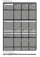
Table Of Contents
- 06230304_MA-PSI9000-2U-TFT-DE
- 1. Allgemeines
- 1.1 Zu diesem Dokument
- 1.2 Gewährleistung und Garantie
- 1.3 Haftungsbeschränkungen
- 1.4 Entsorgung des Gerätes
- 1.5 Produktschlüssel
- 1.6 Bestimmungsgemäße Verwendung
- 1.7 Sicherheit
- 1.8 Technische Daten
- 1.9 Aufbau und Funktion
- 1.9.1 Allgemeine Beschreibung
- 1.9.2 Blockdiagramm
- 1.9.3 Lieferumfang
- 1.9.4 Zubehör
- 1.9.5 Optionen
- 1.9.6 Die Bedieneinheit (HMI)
- 1.9.7 USB-Port (Rückseite)
- 1.9.8 Steckplatz für Schnittstellenmodule
- 1.9.9 Analogschnittstelle
- 1.9.10 Share-Bus-Anschluß
- 1.9.11 Sense-Anschluß (Fernfühlung)
- 1.9.12 Master-Slave-Bus
- 1.9.13 GPIB-Port (optional)
- 2. Installation & Inbetriebnahme
- 2.1 Transport und Lagerung
- 2.2 Auspacken und Sichtkontrolle
- 2.3 Installation
- 2.3.1 Sicherheitsmaßnahmen vor Installation und Gebrauch
- 2.3.2 Vorbereitung
- 2.3.3 Aufstellung des Gerätes
- 2.3.4 Anschließen an das Stromnetz (AC)
- 2.3.5 Anschließen von DC-Lasten
- 2.3.6 Erdung des DC-Ausgangs
- 2.3.7 Anschließen der Fernfühlung
- 2.3.8 Installation eines AnyBus-Schnittstellenmoduls
- 2.3.9 Anschließen der analogen Schnittstelle
- 2.3.10 Anschließen des „Share-Bus“
- 2.3.11 Anschließen des USB-Ports (Rückseite)
- 2.3.12 Erstinbetriebnahme
- 2.3.13 Erneute Inbetriebnahme nach Firmwareupdates bzw. längerer Nichtbenutzung
- 3. Bedienung und Verwendung
- 3.1 Personenschutz
- 3.2 Regelungsarten
- 3.3 Alarmzustände
- 3.4 Manuelle Bedienung
- 3.5 Fernsteuerung
- 3.6 Alarme und Überwachung
- 3.7 Bedieneinheit (HMI) sperren
- 3.8 Nutzerprofile laden und speichern
- 3.9 Der Funktionsgenerator
- 3.9.1 Einleitung
- 3.9.2 Allgemeines
- 3.9.3 Arbeitsweise
- 3.9.4 Manuelle Bedienung
- 3.9.5 Sinus-Funktion
- 3.9.6 Dreieck-Funktion
- 3.9.7 Rechteck-Funktion
- 3.9.8 Trapez-Funktion
- 3.9.9 DIN 40839-Funktion
- 3.9.10 Arbiträr-Funktion
- 3.9.11 Rampen-Funktion
- 3.9.12 UI- und IU-Tabellenfunktion (XY-Tabelle)
- 3.9.13 PV-Tabellenfunktion (Photovoltaik)
- 3.9.14 FC-Tabellenfunktion (Brennstoffzelle)
- 3.9.15 Fernsteuerung des Funktionsgenerators
- 3.10 Weitere Anwendungen
- 4. Instandhaltung & Wartung
- 5. Zubehör und Optionen
- 6. Service & Support
- 1. Allgemeines
- 06230304_MA-PSI9000-2U-TFT-EN
- 1. General
- 1.1 About this document
- 1.2 Warranty
- 1.3 Limitation of liability
- 1.4 Disposal of equipment
- 1.5 Product key
- 1.6 Intended usage
- 1.7 Safety
- 1.8 Technical Data
- 1.9 Construction and function
- 1.9.1 General description
- 1.9.2 Block diagram
- 1.9.3 Scope of delivery
- 1.9.4 Accessories
- 1.9.5 Options
- 1.9.6 The control panel (HMI)
- 1.9.7 USB port (rear side)
- 1.9.8 Interface module slot
- 1.9.9 Analog interface
- 1.9.10 Share Bus-Connection
- 1.9.11 Sense connector (remote sensing)
- 1.9.12 Master-Slave bus
- 1.9.13 GPIB port (optional)
- 2. Installation & commissioning
- 2.1 Transport and storage
- 2.2 Unpacking and visual check
- 2.3 Installation
- 2.3.1 Safety procedures before installation and use
- 2.3.2 Preparation
- 2.3.3 Installing the device
- 2.3.4 Connection to AC supply
- 2.3.5 Connection to DC loads
- 2.3.6 Grounding of the DC output
- 2.3.7 Connection of remote sensing
- 2.3.8 Installation of an AnyBus interface module
- 2.3.9 Connecting the analog interface
- 2.3.10 Connecting the “Share” bus
- 2.3.11 Connecting the USB port (rear side)
- 2.3.12 Initial commission
- 2.3.13 Commission after a firmware update or a long period of non-use
- 3. Operation and application
- 3.1 Personal safety
- 3.2 Operating modes
- 3.3 Alarm conditions
- 3.4 Manual operation
- 3.5 Remote control
- 3.6 Alarms and monitoring
- 3.7 Control panel (HMI) lock
- 3.8 Loading and saving a user profile
- 3.9 The function generator
- 3.9.1 Introduction
- 3.9.2 General
- 3.9.3 Method of operation
- 3.9.4 Manual operation
- 3.9.5 Sine wave function
- 3.9.6 Triangular function
- 3.9.7 Rectangular function
- 3.9.8 Trapezoidal function
- 3.9.9 DIN 40839 function
- 3.9.10 Arbitrary function
- 3.9.11 Ramp Function
- 3.9.12 UI and IU table functions (XY table)
- 3.9.13 PV table function (photovoltaics)
- 3.9.14 FC table function (fuel cell)
- 3.9.15 Remote control of the function generator
- 3.10 Other applications
- 4. Service and maintenance
- 5. Accessories and options
- 6. Service & Support
- 1. General

Page 14
PSI 9000 2U Series
www.elektroautomatik.de
ea1974@elektroautomatik.de
EA Elektro-Automatik GmbH
Helmholtzstr. 31-33 • 41747 Viersen
Germany
Fon: +49 2162 / 3785-0
Fax: +49 2162 / 16230
(1 Related to the nominal values, the accuracy denes the maximum deviation between an adjusted values and the true (actual) value.
Example: a 80 V model has min. 0.1% voltage accuracy, that is 80 mV. When adjusting the voltage to 5 V, the actual value is allowed to differ max. 80 mV, which
means it might be between 4.92 V and 5.08 V.
(2 RMS value: LF 0...300 kHz, PP value: HF 0...20MHz
(3 Typical value at 100% output voltage and 100% power
(4 The display error adds to the error of the related actual value on the DC output
1500 W
Model 2U
PSI 9040-60 PSI 9080-60 PSI 9200-25
AC Input
Input voltage 90...264 V AC 90...264 V AC 90...264 V AC
- with additional derating 90...150 V AC 90...150 V AC 90...150 V AC
Input connection 1ph,N,PE 1ph,N,PE 1ph,N,PE
Input frequency 50/60 Hz 50/60 Hz 50/60 Hz
Input fuse (internal) T16 A T16 A T16 A
Leak current < 3.5 mA < 3.5 mA < 3.5 mA
Power factor ~ 0.99 ~ 0.99 ~ 0.99
DC Output
Max. output voltage U
Max
40 V 80 V 200 V
Max. output current I
Max
60 A 60 A 25 A
Max. output power P
Max
1500 W 1500 W 1500 W
Max. output power P
Max
with derating 1000 W 1000 W 1000 W
Overvoltage protection range 0...44 V 0...88 V 0...220 V
Overcurrent protection range 0...66 A 0...66 A 0...27.5 A
Overpower protection range 0…1650 W 0…1650 W 0…1650 W
Temperature coefcient for set
values Δ/K
Voltage / current: 100 ppm
Voltage regulation
Adjustment range 0..40 V 0...80 V 0...200 V
Accuracy
(1
(at 23 ± 5°C) < 0.1% U
Nom
< 0.1% U
Nom
< 0.1% U
Nom
Stability at ±10% ΔU
AC
< 0.02% U
Nom
< 0.02% U
Nom
< 0.02% U
Nom
Stability at 0...100% load < 0.05% U
Nom
< 0.05% U
Nom
< 0.05% U
Nom
Rise time 10...90% Max. 30 ms Max. 30 ms Max. 30 ms
Display: Resolution See section „1.9.6.4. Resolution of the displayed values“
Display: Accuracy
(4
≤ 0.2% U
Nom
≤ 0.2% U
Nom
≤ 0.2% U
Nom
Ripple
(2
< 114 mV
PP
< 8 mV
RMS
< 114 mV
PP
< 8 mV
RMS
< 164 mV
PP
< 34 mV
RMS
Remote sensing compensation Max. 5% U
Nom
Max. 5% U
Nom
Max. 5% U
Nom
Output voltage fall time (at no load)
after switching DC output off
- -
Down from 100% to
<60 V: less than 10 s
Current regulation
Adjustment range 0...60 A 0...60 A 0...25 A
Accuracy
(1
(at 23 ± 5°C) < 0.2% I
Nom
< 0.2% I
Nom
< 0.2% I
Nom
Stability at ±10% ΔU
AC
< 0.05% I
Nom
< 0.05% I
Nom
< 0.05% I
Nom
Stability at 0...100% ΔU
OUT
< 0.15% I
Nom
< 0.15% I
Nom
< 0.15% I
Nom
Ripple
(2
< 79 mA
PP
< 79 mA
PP
< 16 mA
PP
Display: Resolution See section „1.9.6.4. Resolution of the displayed values“
Display: Accuracy
(4
≤ 0.2% I
Nom
≤ 0.2% I
Nom
≤ 0.2% I
Nom
Compensation 10%->90% load < 1.5 ms < 1.5 ms < 1.5 ms
Power regulation
Adjustment range 0…1500 W 0…1500 W 0…1500 W
Accuracy
(1
(at 23 ± 5°C) < 1% P
Nom
< 1% P
Nom
< 1% P
Nom
Stability at ±10% ΔU
AC
< 0.05% P
Nom
< 0.05% P
Nom
< 0.05% P
Nom
Stability at 10-90% ΔU
OUT
* ΔI
OUT
< 0.75% P
Nom
< 0.75% P
Nom
< 0.75% P
Nom
Display: Resolution See section „1.9.6.4. Resolution of the displayed values“
Display: Accuracy
(4
≤ 0.8% P
Nom
≤ 0.8% P
Nom
≤ 0.7% P
Nom
Efciency
(3
~ 92% ~ 92% ~ 93%