
User manual


Table Of Contents
- 06230304_MA-PSI9000-2U-TFT-DE
- 1. Allgemeines
- 1.1 Zu diesem Dokument
- 1.2 Gewährleistung und Garantie
- 1.3 Haftungsbeschränkungen
- 1.4 Entsorgung des Gerätes
- 1.5 Produktschlüssel
- 1.6 Bestimmungsgemäße Verwendung
- 1.7 Sicherheit
- 1.8 Technische Daten
- 1.9 Aufbau und Funktion
- 1.9.1 Allgemeine Beschreibung
- 1.9.2 Blockdiagramm
- 1.9.3 Lieferumfang
- 1.9.4 Zubehör
- 1.9.5 Optionen
- 1.9.6 Die Bedieneinheit (HMI)
- 1.9.7 USB-Port (Rückseite)
- 1.9.8 Steckplatz für Schnittstellenmodule
- 1.9.9 Analogschnittstelle
- 1.9.10 Share-Bus-Anschluß
- 1.9.11 Sense-Anschluß (Fernfühlung)
- 1.9.12 Master-Slave-Bus
- 1.9.13 GPIB-Port (optional)
- 2. Installation & Inbetriebnahme
- 2.1 Transport und Lagerung
- 2.2 Auspacken und Sichtkontrolle
- 2.3 Installation
- 2.3.1 Sicherheitsmaßnahmen vor Installation und Gebrauch
- 2.3.2 Vorbereitung
- 2.3.3 Aufstellung des Gerätes
- 2.3.4 Anschließen an das Stromnetz (AC)
- 2.3.5 Anschließen von DC-Lasten
- 2.3.6 Erdung des DC-Ausgangs
- 2.3.7 Anschließen der Fernfühlung
- 2.3.8 Installation eines AnyBus-Schnittstellenmoduls
- 2.3.9 Anschließen der analogen Schnittstelle
- 2.3.10 Anschließen des „Share-Bus“
- 2.3.11 Anschließen des USB-Ports (Rückseite)
- 2.3.12 Erstinbetriebnahme
- 2.3.13 Erneute Inbetriebnahme nach Firmwareupdates bzw. längerer Nichtbenutzung
- 3. Bedienung und Verwendung
- 3.1 Personenschutz
- 3.2 Regelungsarten
- 3.3 Alarmzustände
- 3.4 Manuelle Bedienung
- 3.5 Fernsteuerung
- 3.6 Alarme und Überwachung
- 3.7 Bedieneinheit (HMI) sperren
- 3.8 Nutzerprofile laden und speichern
- 3.9 Der Funktionsgenerator
- 3.9.1 Einleitung
- 3.9.2 Allgemeines
- 3.9.3 Arbeitsweise
- 3.9.4 Manuelle Bedienung
- 3.9.5 Sinus-Funktion
- 3.9.6 Dreieck-Funktion
- 3.9.7 Rechteck-Funktion
- 3.9.8 Trapez-Funktion
- 3.9.9 DIN 40839-Funktion
- 3.9.10 Arbiträr-Funktion
- 3.9.11 Rampen-Funktion
- 3.9.12 UI- und IU-Tabellenfunktion (XY-Tabelle)
- 3.9.13 PV-Tabellenfunktion (Photovoltaik)
- 3.9.14 FC-Tabellenfunktion (Brennstoffzelle)
- 3.9.15 Fernsteuerung des Funktionsgenerators
- 3.10 Weitere Anwendungen
- 4. Instandhaltung & Wartung
- 5. Zubehör und Optionen
- 6. Service & Support
- 1. Allgemeines
- 06230304_MA-PSI9000-2U-TFT-EN
- 1. General
- 1.1 About this document
- 1.2 Warranty
- 1.3 Limitation of liability
- 1.4 Disposal of equipment
- 1.5 Product key
- 1.6 Intended usage
- 1.7 Safety
- 1.8 Technical Data
- 1.9 Construction and function
- 1.9.1 General description
- 1.9.2 Block diagram
- 1.9.3 Scope of delivery
- 1.9.4 Accessories
- 1.9.5 Options
- 1.9.6 The control panel (HMI)
- 1.9.7 USB port (rear side)
- 1.9.8 Interface module slot
- 1.9.9 Analog interface
- 1.9.10 Share Bus-Connection
- 1.9.11 Sense connector (remote sensing)
- 1.9.12 Master-Slave bus
- 1.9.13 GPIB port (optional)
- 2. Installation & commissioning
- 2.1 Transport and storage
- 2.2 Unpacking and visual check
- 2.3 Installation
- 2.3.1 Safety procedures before installation and use
- 2.3.2 Preparation
- 2.3.3 Installing the device
- 2.3.4 Connection to AC supply
- 2.3.5 Connection to DC loads
- 2.3.6 Grounding of the DC output
- 2.3.7 Connection of remote sensing
- 2.3.8 Installation of an AnyBus interface module
- 2.3.9 Connecting the analog interface
- 2.3.10 Connecting the “Share” bus
- 2.3.11 Connecting the USB port (rear side)
- 2.3.12 Initial commission
- 2.3.13 Commission after a firmware update or a long period of non-use
- 3. Operation and application
- 3.1 Personal safety
- 3.2 Operating modes
- 3.3 Alarm conditions
- 3.4 Manual operation
- 3.5 Remote control
- 3.6 Alarms and monitoring
- 3.7 Control panel (HMI) lock
- 3.8 Loading and saving a user profile
- 3.9 The function generator
- 3.9.1 Introduction
- 3.9.2 General
- 3.9.3 Method of operation
- 3.9.4 Manual operation
- 3.9.5 Sine wave function
- 3.9.6 Triangular function
- 3.9.7 Rectangular function
- 3.9.8 Trapezoidal function
- 3.9.9 DIN 40839 function
- 3.9.10 Arbitrary function
- 3.9.11 Ramp Function
- 3.9.12 UI and IU table functions (XY table)
- 3.9.13 PV table function (photovoltaics)
- 3.9.14 FC table function (fuel cell)
- 3.9.15 Remote control of the function generator
- 3.10 Other applications
- 4. Service and maintenance
- 5. Accessories and options
- 6. Service & Support
- 1. General
Page 48
PSI 9000 2U Series
www.elektroautomatik.de
ea1974@elektroautomatik.de
EA Elektro-Automatik GmbH
Helmholtzstr. 31-33 • 41747 Viersen
Germany
Fon: +49 2162 / 3785-0
Fax: +49 2162 / 16230
3.4.3.2 Menu “User Events”
See „3.6.2.1 User dened events“ on page 60.
3.4.3.3 Menu “Proles”
See „3.8 Loading and saving a user prole“ on page 61.
3.4.3.4 Menu “Overview”
This menu page displays an overview of the set values (U, I, P or U, I, P, R) and alarm settings as well as settings
limits. These can only be displayed, not changed.
3.4.3.5 Menu “About HW, SW...”
This menu page displays an overview of device relevant data such as serial number, article number etc., as well as
an alarm history which lists the number of device alarms that probably occurred since the device has been powered.
3.4.3.6 Menu “Function Generator”
See „3.9 The function generator“ on page 62.
3.4.3.7 Menu “Communication”
This submenu offers settings for digital communication via the optional or built-in interface. The button for the
Anybus modules (Anybus symbol) or the optional GPIB port opens one or more settings pages, depending on the
interface in use. There is furthermore an adjustable communication timeout, to make it possible to successfully
transfer fragmented messages (data packets) using higher values. In the screen for “Com Protocols” you can
enable both or disable one of the two supported communication protocols, ModBus and SCPI. This can help to
avoid mixing both protocols and to receive unreadable messages, for example when expecting a SCPI response
and getting a ModBus response instead.
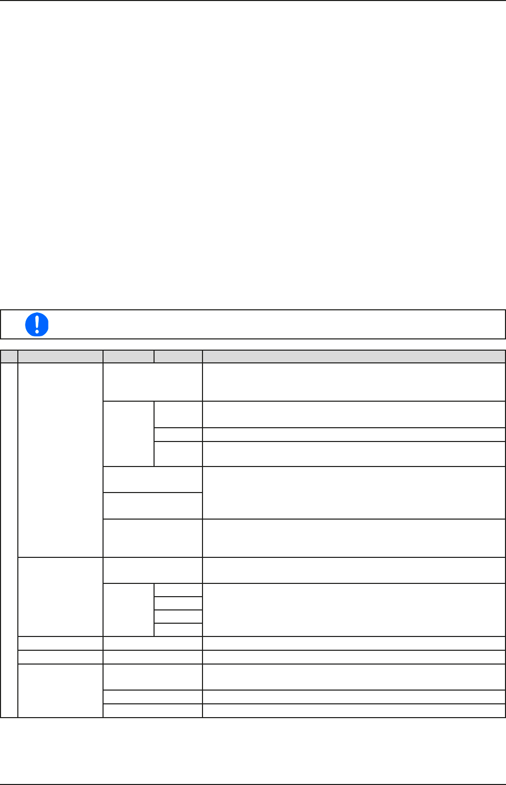
For all Ethernet interfaces with two ports: „P1“ is related to port 1 and „P2“ to port 2, like printed
on the module face. Two-port interfaces will use one IP only.
IF Level 1 Level 2 Level 3 Description
Ethernet / ModBus-TCP, 1 & 2 Port
IP Settings DHCP The IF allows a DHCP server to allocate an IP address, a subnet
mask and a gateway. If no DHCP server is in the network then net-
work parameters will be set as dened in item “Manual”
Manual IP This option is activated by default. An IP address can be maually
allocated.
Gateway Here a gateway address can be allocated if required..
Subnet Here a subnet mask can be dened if the default subnet mask is
not suitable.
DNS 1 Here the addresses of the rst and second Domain Name Servers
(DNS) can be dened, if needed. A DNS is only necessary if the
device has Internet access and should call Internet URLs, e.g. an
internal eMail system, in order to send an eMail.
DNS 2
Port Range: 0...65535. Default ports:
5025 = Modbus RTU (all Ethernet interfaces)
502 = Modbus TCP (Modbus-TCP interface only)
IP Com
Settings P1
IP Com
Settings P2
AUTO Settings for the Ethernet port such as transmission speed are set
automatically.
Manual Half dup Manual selection for transmission speed (10MBit/100MBit) and
duplex mode (full/half). It is recommended to use the “AUTO” option
and only revert to “Manual” if these parameters fail.
Full dup
10MBit
100MBit
Host name Free choice of host name (default: Client)
Domain name Free choice of Domain (default: Workgroup)
SMTP
Settings
Server IP Mail server address, used to send eMails via this mail server, in
order to e.g. report an alarm.
Username Login to Mailserver, Username
Password Login to Mailserver, Password