
User manual


Page 36
PS 9000 2U Series
www.elektroautomatik.de
ea1974@elektroautomatik.de
EA Elektro-Automatik GmbH
Helmholtzstr. 31-33 • 41747 Viersen
Germany
Fon: +49 2162 / 3785-0
Fax: +49 2162 / 16230
2.3.7 Connection of remote sensing
In order to compensate, to a certain degree, the voltage loss in a DC cable, the device provides the possibility to
connect the remote sensing input “Sense” to the load. The device recognizes the remote sensing mode automati-
cally and regulates the output voltage (only in CV operation) at the load rather than at its own DC output.
In the technical specications (see section „1.8.3. Specic technical data“) the level of maximum possible com-
pensation is given. If that is insufcient, the cable cross section must be increased.
Both pins „NC“ of the Sense connector must not be wired!
• The cross section of the sense cables is noncritical. However, it should be increased with
increasing cable length. Recommendation: for cables up to 5 m use at least 0.5 mm²
• Sense cables should be twisted and laid close to the DC cables to damp oscillation. If neces-
sary, an additional capacitor should be installed at the load/consumer to eliminate oscillation
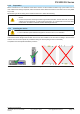
• The sense cables must be connected + to + and - to - at the load, otherwise both systems
may be damaged
Figure 7 - Example for remote sensing wiring
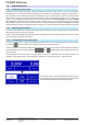
2.3.8 Connecting the “Share” bus
The “Share” connector on the back side is intended to balance the current of multiple units in parallel operation,
especially when using the integrated function generator of the master unit. For further information about this mode
of operation can be found in section „3.9.1. Parallel operation in Share Bus mode“ .
For the connection of the share bus the following must be paid attention to:
Connection is only permitted between compatible devices (see „1.9.10. Share Bus-Connection“
for details) and between a max. of 10 units
2.3.9 Connecting the analog interface
The 15 pole connector (Type: Sub-D, D-Sub) on the rear side is an analog interface. To connect this to a control-
ling hardware (PC, electronic circuit), a standard plug is necessary (not included in the scope of delivery). It is
generally advisable to switch the device completely off before connecting or disconnecting this connector, but at
least the DC output.
The analog interface is galvanically isolated from the device internally. Therefore do not con-
nect any ground of the analog interface (AGND) to the DC minus output as this will cancel the
galvanic isolation.