
Specifications


and warm soapy water. Residual corrosion and acid spillover
can be removed with a baking soda and water mixture using
one small box of soda to one gallon of water. Remember,
battery acid can be very damaging… wear rubber gloves,
eye protection, and old clothes. Work in a well-ventilated
and appropriate area for the task. Battery residue can stain
concrete. Next, re-face the contact surfaces of your battery
terminals, as this will ensure good electrical contact with the
new cables of your Performance Enhancement kit. While
this can be done with a wire brush, the best tool for this task
is our battery terminal re-facer, which insures a fl at, smooth
surface and maximum electrical contact between the terminal
and the battery. Also, inspect the battery-water level in each
cell of each battery and fi ll to the proper level. While the
caps are off, wipe them with a moist rag and inspect them for
cracks, clogged ventilation holes, or other damage. Lastly,
check the condition of the battery hold-down bolts. If they are
damaged, or corroded, replace them now. Once these steps are
completed, you may install the batteries into the battery tray,
remembering the importance of arranging the batteries just as
they were when you removed them. Generally, it is easier to
fi rst install the three batteries to the rear of the cart, followed
9
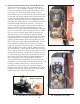
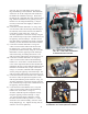
12. Battery Installation
Battery Strap
by the three batteries in the front. The battery hold-down bolts create a bit of a balancing act, but with a little
patience and persistence you will have all six batteries installed, and you will be able to set the hold-down
plate over the bolts and secure them using the factory hardware and a 1/2” or 9/16” wrench.
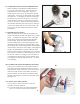
13) BATTERY WIRING:
A note on battery wiring: With new cables and re-faced battery posts, you are prepared to make an excellent
connection at each battery post. The last factor in a great connection is a good tight fi t of the terminal to
the post. You will want to tighten all of your lug nuts securely (90-110 inch lbs.), but avoid over tightening.
Putting too much effort into securing the nuts can distort the battery plates and care should be given to
supporting the post while tightening. Stripped threads will lead to loose connections, increased heat, and
premature failure. Battery lug nuts typically require 1/2” or 9/16” sockets… use whatever size socket fi ts
your particular application.
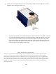
a) Locate the four (4) cables, which are 7” long. Using the Heavy Gauge Wiring Diagram for reference
(pg. 12), install one cable between the negative terminal of battery #1 and the positive terminal of
battery #2. Install another 7” cable between the negative terminal of battery #2 and the positive terminal
of battery #3. Install another 7” cable between the negative terminal of battery #4 and the positive
terminal of battery #5. Install the last 7” cable between the negative terminal of battery #5 and the
positive terminal of battery #6. Tighten securely using the above-mentioned cautions.
b) Locate the cable, which is 11” long. Using the wiring diagram for reference, install this cable between
the negative terminal of battery #3 and the positive terminal of battery #4.
c) Before proceeding, insure that the key is removed from the ignition switch.
d) Locate the 21” long red coded cable, which you installed in step 11b. Connect the free end of this cable
to the positive terminal on battery #1. It is critical that this connection is made accurately! This wire
should run only from the battery side (or passenger side) large threaded lug of the solenoid directly to
the positive terminal of battery #1. Double-check your work before proceeding.
e) Locate the 29” long black coded cable, which you installed in step 11j. Connect the free end of this
cable to the negative terminal on battery #6. It is critical that this connection is made accurately!
This wire should run only from the “B-” buss bar of the speed controller to the negative terminal of
battery #6. Double-check your work before proceeding.