
Specifications


each end. This wire will jumper across the two
large threaded lugs of the solenoid. Recall that the
solenoid is one of the components which will have
the double nuts installed on the lugs. Ensure that
the bottom nut is threaded onto each of the two large
lugs, and then install the wire by placing one ring
terminal over each large threaded lug. It may be
necessary to bend the wire slightly to make it fit…
this is normal.
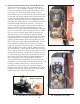
b) Locate the red coded cable that is 27” long. Place
one end of this cable onto the large threaded lug of
the solenoid, which will be closest to the batteries
(or the driver’s side of the cart). Using 1/2”
wrenches, tighten the connection securely using the
lock washer and top nut provided. Remember to use
the opposing wrench technique. The other end of
this cable will be connected to the positive terminal
of battery #1 after the batteries have been installed.
c) Locate the red coded cable that is 8” long and
connect one end of this cable to the electric buss
bar marked “B+” on the controller. Tighten the
provided nut and bolt securely using 1/2” wrenches.
Remember to use the opposing wrench technique
and avoid twisting or bending the buss bar. The
other end of this cable will be connected in step 11e.
d) Locate the red coded cable that is 54” long and
connect one end of this cable to the threaded lug
marked “A1” on the motor. Recall that the motor
is one of the components that will have double nuts
installed on the lugs. Ensure that the bottom nuts are
threaded on each of the four (4) lugs of the motor.
Using 1/2” wrenches, install the cable and tighten
securely using the opposing wrench technique. The
other end of this cable will be connected in step 11e.
e) Locate the unconnected ends of the red 8” cable and
the red 54” cable, and place them together on the
other large threaded lug of the solenoid. Using 1/2”
wrenches, tighten the connection securely using the
lock washer and top nut provided. Remember to use
the opposing wrench technique.
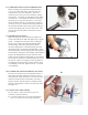
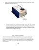
f) Locate the blue coded cable that is 47” long and
connect one end of this cable to the threaded lug
marked “A2” on the motor. Using 1/2”
wrenches, install the top nut and tighten securely
using the opposing wrench technique. Using a
1/2” wrench and the factory hardware, connect
the other end of this cable to position “C” of the
forward/reverse switch assembly, as shown on the
wiring diagram (pg. 12). Tighten securely, but use
caution to avoid over tightening.
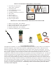
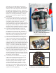
11a. Resistor Installation
11b,c & e. Red Cable Installation
on Solenoid and Controller
11d,f,h & i. Motor Cable Installation
11f,g & h. Blue, Green & Orange Cable
Installation on Forward/Reverse Switch
Resistor
A
B
C
D
7