
Specifications

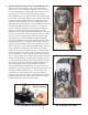

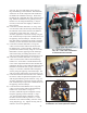


5) FORWARD/REVERSE SWITCH WIRE REMOVAL:
Locate the forward/reverse switch assembly, which is found
directly in front of the speed controller mounting area.
Remove all four heavy gauge cables from the switch assembly
and retain the factory hardware for reinstallation of your
new cables. See the wiring diagram (pg. 12) for a visual
representation of the forward/reverse switch assembly.
6) FINAL CABLE REMOVAL:
You will find four (4) large threaded electrical lugs on the case
of the motor, with one cable connected to each lug. Remove
these cables, remembering to use the opposing wrench
technique. Once you have removed the cables from the motor,
all of the heavy gauge cables in your cart should now be
disconnected from their mounting points, and you may remove
them from the cart, while taking note of the paths in which
they were routed.
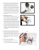
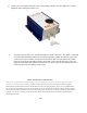
7) MOTOR REMOVAL:
Before removing the motor, clean the surrounding area of any
excessive mud or dirt, which may have accumulated on nearby
parts. We want to ensure that internal parts stay as clean as
possible. Once the area is clean, you will notice three hex
head bolts on the differential case, which bolt through to the
motor. Using a 7/16” socket, remove these bolts to release
the motor from the housing. If your cart has a cable-retaining
loop fastened to one of the motor mount bolts, release that
bolt first, and then remove the remaining two bolts. Carefully
pull the motor from the housing. Some gentle back and forth
pressure, while pulling the motor, should allow the motor to
slide off the shaft. Use caution, as the motor is heavy and will
drop quickly once it is free from the shaft.
5. Forward & Reverse Assembly
6. Opposing Wrench Technique
7. Gentle Back and Forth Pressure To Remove Motor
Motor
Differential
Case
5