Class 5000 Meter ADVANCED KWH/DEMAND METER INSTALLATION INSTRUCTIONS E-Mon 850 Town Center Drive Langhorne, PA 19047 (800) 334-3666 www.emon.com info@emon.
CLASS 5000 METER Dear Valued Customer, We are pleased that you chose to buy one of our products, and want you to be just as pleased with owning it. Before installing your new E-Mon product, please read the information on the following pages carefully. We believe that you will find the E-Mon D-Mon meters easy to install and to use for monitoring and evaluating your electrical usage.
CLASS 5000 METER TABLE OF CONTENTS Section 1.0 Introduction 4 Section 2.0 Internal Electronic Assemblies 5 Section 2.1 Main Power Board Section 2.2 Display Board 7 Section 2.3 Input Board 8 Section 2.4 6 Pulse Type and Value 9 Section 3.0 Meter Technical Specifications 9 Section 4.0 Safety Label Definitions and Information 12 Section 5.0 Precautionary/Safety Information 12 Section 6.0 Meter Installation 13 Section 6.1 Mounting the Class 5000 Meter 13 Section 6.
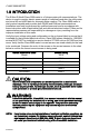
CLASS 5000 METER 1.0 INTRODUCTION The E-Mon D-Mon® Class 5000 meter is a 3-phase meter with communications. The device is used to monitor electric power usage of individual loads after the utility meter and store kW and kVAR data for automatic meter reading. The Class 5000 meter is dual protocol capable and provides both RS485 and Ethernet communications.
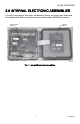
CLASS 5000 METER 2.0 INTERNAL ELECTRONIC ASSEMBLIES The unit is comprised of two major subassembly boards, the main power board and the display board. Both circuit boards are mounted inside a NEMA 4X enclosure. MAIN POWER BOARD DISPLAY BOARD M33270 Fig. 1. Internal Electronic Assemblies.
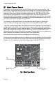
CLASS 5000 METER 2.1 Main Power Board Connections to this board include the MAIN Power Input and current sensors. The MAIN Power Input terminals are positions one through four on the four position screw terminal block, TB1. These terminals are covered with a protective shield for safety purposes. The current sensor assemblies interface to the TB2, TB3 and TB4.
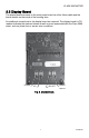
CLASS 5000 METER 2.2 Display Board The display board connects to the main power board via a flex ribbon cable and the board mounts on the inside of the housing door. No additional connections to the display board are required. The display board’s LCD readout indicates the metered values as well as errors associated with the Class 5000 meter, such as phase loss or sensor error conditions. DOWN UP SELECT MENU M33279 Fig. 3. Display Board.
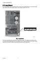
CLASS 5000 METER 2.3 Input Board The Class 5000 meter is supplied with an input board which allows it to accept pulses (dry contact) from third party meters, such as gas, water, BTU, etc. + INP1 + INP2 + OUT1 + OUT2 INPUT TERMINALS CL5000 METER INPUT BOARD M33272 Fig. 4. Input Board. The input terminals are used by the Class 5000 meter. The output terminals are not. Connect metering devices with “dry contacts” only.
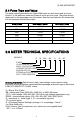
CLASS 5000 METER 2.4 Pulse Type and Value The pulse outputs provided by the Class 5000 meter are watt-hours and var-hours. Output 1 is the watt-hour pulse and Output 2 is the var-hour pulse. The pulse value is dependant on the amperage size of the meter. See the chart below for the values also true for expansion board pulse output. Meter Amps Watt-hours / pulse Var-hours / pulse 100 1.95313 1.95313 200 3.90625 3.90625 400 7.8125 7.8125 800 15.625 15.625 1800 31.25 31.25 3200 62.5 62.
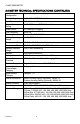
CLASS 5000 METER 3.0 METER TECHNICAL SPECIFICATIONS (CONTINUED) Input Voltage Configuration 3-wire (Delta) Or 4-wire (Wye) Mains Voltage Input Up To 480 VAC RMS Available Input Power 6 VA Maximum Rating Current Sensor Rating Up To 3200 Amps RMS AC Available Power Factor 0.5 Leading Or Lagging Line Frequency 50-60 Hz Metering Accuracy Certified To ANSI C12.
CLASS 5000 METER Modem Interface IDR Interface Port Cable: UL-listed Telephone Cord, 6-cond. 300 VAC, Stranded Cond. 22-26 AWG. Cable Connector: RJ-45 male IDC Input/Output Voltage: +5 VDC/18 VAC Ckt Input Isolation 5.3K VAC for 1 Minute Baud Rate: 9600 Cable: UL-listed/rated Telephone Cord. 4-cond. Input/output Voltage: Ground-isolated +/-5.4VDC Cable Connector: RF-45 Male IDC Or Screw Terminal Termination Circuit Input Isolation: 5.3kVAC Circuit output Isolation: 21.
CLASS 5000 METER 4.0 SAFETY LABEL DEFINITIONS AND INFORMATION The 5000 meter may contain one or more of the following labels. Operator(s) should familiarize themselves with the meaning of each label to minimize risk. The presence of this label is a cautionary indicator identifying a danger risk. The manual should be consulted prior to proceeding. The presence of this label indicates an electrical shock hazard exists in the location or area where the label is placed.
CLASS 5000 METER 6.0 METER INSTALLATION 6.1 Mounting the Class 5000 Meter 6-35/64 (166) 5/8 (16) 6-35/64 (166) 7-51/64 (198) 3-17/64 (83) Ø 1-3/32 (28) THROUGH NEAR SIDE ONLY 3-25/64 (86) 1-5/8 (41) M34684 Fig. 5. Enclosure Dimensions Use appropriately sized mounting hardware to fasten the meter enclosure to the selected mounting surface. The four housing mounting holes are centered 6.75” H x 4” W.
CLASS 5000 METER 6.2 Main Power Board Connections 1. 2. Installing a temporary ground for ESD protection: With all circuits de-energized, connect a temporary protective earth ground connection for ESD protection. Prior to performing any unit wiring, be sure to discharge any static on your person. Installing the Class 5000 protective earth ground: Connect an earth ground wire to the Class 5000 protective earth ground lug with a torque of 7 N-m. * for meters in metal enclosures.
CLASS 5000 METER c. External Switch Mechanism/In-Line Fuse Installation. To ensure a safe installation, the Class 5000 meter requires an external switch mechanism, such as a circuit breaker, be installed on the Class 5000 MAINS input wiring. The switch mechanism must be installed in close proximity to the meter and easily reachable for the operator. This device must also be marked as the disconnecting device for the Class 5000 meter.
CLASS 5000 METER 6.3 Phasing of Line Voltage The 3-phase AC power input must be in proper phase sequence. Single phase “-SP” option - AC power input must be in proper phase sequence. If the sequence is incorrect or a phase is missing, there will be a message on the meter’s display: “PH Sequence Error” or “PH Missing:. (Refer to the section on Line Voltage Diagnostics if this message is present.) When the line voltage is connected correctly, the meter’s display will be blank (no message.
CLASS 5000 METER 6.4 Current Sensor Installation & Wiring Once the AC voltages have been confirmed to be within acceptable limits, you are ready to install the current sensors. TB2 is the input for Phase A, TB3 is the input for Phase B and TB4 is the Phase C input. For the SP option: use TB1 pos 5&6 are for the A Phase - TB1 pos 7&8 are for the B phase -factory installed jumper wire on positions 9&10. Factory installed Jumper should not be removed.
CLASS 5000 METER LOAD SOURCE M33213 Fig. 8. Installation of a Split Core Sensor. IMPORTANT: When looking from the source side of the conductor(s) being monitored, you should see the arrow on the current sensor assembly. The arrow should be pointing in a clockwise direction around the conductor(s) being monitored. If the arrow is not positioned on the source side, inaccurate readings will result. 6.4.
CLASS 5000 METER 6.4.2 Current Sensor Wiring (continued) If the meter displays an error message (see below), remove the wires from terminals 5 and 6 and install them on terminals 7 and 8 (Phase B). if an error message occurs with the sensor attached to terminals 7 and 8, try again on terminals 9 and 10 (Phase C). The “CT Error: * “message will disappear when the current sensor is connected to the correct terminals (phase).
CLASS 5000 METER 6.5 Main Power & Current Sensor Wiring Diagram TERMINAL BLOCK LOCATED INSIDE E-MON D-MON® METER LINE VOLTAGE ØA ØB ØC N 2 1 1 1 CURRENT SENSORS ØA ØB ØC W B W B W B 3 A 3 B 3 LOAD C N SOURCE 1 RECOMMENDED FUSES OR CIRCUIT BREAKER PER THE NATIONAL ELECTRICAL CODE (METER LOAD 6VA.) 2 NEUTRAL NOT USED IN DELTA SYSTEM. 3 SPLIT-CORE CURRENT SENSORS. INSTALL ACCORDING TO INSTRUCTIONS. M34291 Fig. 9. 3-Phase - 3-Wire or 3-Phase - 4-Wire Installation Diagram.
CLASS 5000 METER 6.6 Line Voltage/Current Sensor Diagnostics Following is a list of diagnostic messages that may appear on the meter display. DIAGNOSTIC MESSAGES SHOULD NOT BE ON CONTINUOUSLY WHEN THE METER IS INSTALLED PROPERLY AND IS IN WORKING ORDER. 6.6.1 Line Voltage Diagnostics The diagnostics program detects line voltage faults by displaying one of two messages: PH Missing: B C or Phase sequence error. PH Missing: B C: Indicates that the line voltage is missing on Phase B and/or Phase C.
CLASS 5000 METER 6.6.2 Current Sensor Diagnostics The load current must be at least 1% of the meter’s rated load in order to use the diagnostic function. Current sensor diagnostics can detect: 1. 2. 3. Reversed current sensors Incorrect phase correspondence Unusually low power factor (0.642 or lower) CT Error: (ABC) is used to detect the swapping of current sensor phases. This message could (in some rare cases) indicate a low (<65%) power factor condition.
CLASS 5000 METER 6.7 RS-485 Wiring RS-485 communication allows a computer or modem to communicate with one or more Class 5000 meters. You can connect as many as 52 meters along a 4000-foot RS-485 cable run. There are four communication protocols available through the Class 5000 RS-485 connection. They are EZ7, Modbus RTU, BACnet MS/TP, and Lonworks FT-10. The protocol is chosen when ordering the Class 5000 meter. A second protocol is available through the Ethernet port.
CLASS 5000 METER 6.7 RS-485 Wiring (continued) After performing these steps, all of the meters will be connected in a daisy chain configuration. This network of meters can then be connected to the RS-485 network and communication can be established. Internal Modem An optional internal modem inside one meter will communicate with the others via the RS-485 network. Simply connect one of the two telephone jacks on the modem to the telephone line to complete the installation.
CLASS 5000 METER 6.8 RS-232 Communications 6.8.1 Hardwired System using the RS-232 Communication Key The RS-232 communications key allows you to connect Class 5000 meters to a personal computer that has the E-Mon Energy™ software installed. The computer communicates with the meters through the RS-232 key. The RS-232 key must be located within 15 feet of the host computer.
CLASS 5000 METER NOTE: When the E-Mon Energy™ software is accessed on the computer, a third LED (RS232 READY) will turn on. This indicator will light up as soon as the E-Mon Energy software is booted up and the correct COM port is set up via the settings provided in the software’s Locations menu. 6.8.3 Connecting Class 5000 Meters to the RS-232 Key using RS-485 On the rear panel of the RS-232 key, there are three jacks labeled as channels A, B and C.
CLASS 5000 METER 6.9 Modem Wiring RS-232 SERIAL PORT COM1 THROUGH COM3 MAXIMUM 15 FEET CHANNEL 1 LOCAL MODEM ~ ~ PC OR WINDOWS COMPATIBLE TELEPHONE LINK UP TO 4000 FEET TOTAL ~ UP TO 52 ~ CLASS 5000 METERS PER CHANNEL RS-232 KEY RM CHANNEL 2 AC ADAPTER CHANNEL 3 UP TO 4000 FEET TOTAL ~ UP TO 52 ~ CLASS 5000 METERS PER CHANNEL M33276 Fig. 14. Modem Configuration. 6.9.
CLASS 5000 METER 6.9.2 External Modem 1. 2. 3. 4. 5. All meters should be connected to the RS-232 key as described in 6.8.2. 2. DISCONNECT POWER TO THE RS-232 KEY. Remove the cover by removing the 2 screws from the bottom of the enclosure. On the circuit board, locate the blue jumpers J7 (MODEM) and J8 (ex-MODEM). If these jumpers are set in the DIRECT position, you must move the jumpers so they are set in the MODEM position. Re place the cover and secure the enclosure.
CLASS 5000 METER 6.9.3 Baud Rate Selection The communication baud rate is selected by means of a jumper on the circuit board. There are four (4) selections: 9600 (factory default), 19200, 38400, and 76800. 1. 2. 3. 4. 5. 6. Select 9600 when using the Class 5000 meter with a modem. The baud rate on the meter must always match the baud rate selected in the EMon Energy software; otherwise, communications will not work. After a baud rate change, press CPU Reset to register the change.
CLASS 5000 METER 6.9.
CLASS 5000 METER 6.10 Modbus RTU Wiring The Class 5000 Modbus meter communicates with building automation equipment over a 2-wire (3-conductor) RS-485 network using Modbus RTU protocol. The meters are networked in a daisy-chain configuration (Section 6.7) with BELDEN 1120A cable or equivalent. The cable rating of 600V allows the RS-485 network to be connected to 480-volt meters. Up to 52 meters can be installed on a network string.
CLASS 5000 METER 6.12 Connecting Class 5000 Meters to the USB Key using RS485 The USB Key plugs into the PC’s USB port and provides a termination point for the RS485 wiring from the meters. Up to 52 meters can be “Daisy chained” with up to 4000 feet total RS485 wiring. The USB Key is labeled for “plus (+)”, “minus (-)“, and ground and the wiring must match the same positions on the meters. If more than 52 meters are to be monitored, additional USB Keys can be utilized to connect them to the PC.
CLASS 5000 METER 6.13 Ethernet Communications Ethernet/IP communications connections are provided through an RJ-45 connector(J8) in the lower right corner of the main power board. This port can be connected directly to a network port of a PC using a Cat. 5e crossover cable. Two LEDs are provided directly above the connector. The LINK LED is yellow and when lit, indicates ethernet connectivity. The ACT led is green and when lit, indicates communication activity.
CLASS 5000 METER 7.0 MULTIPLE-LOAD MONITORING The E-Mon D-Mon Class 5000 meter provides extreme flexibility by allowing additional sets of current sensors to be used in parallel so multiple load locations can be monitored by one meter. This feature allows a totalized display readout from two or more load circuits. You may use parallel sensors to monitor specific breakers from one panel, specific breakers from more than one panel, two or more complete panels, etc.
CLASS 5000 METER LINE VOLTAGE CURRENT SENSORS ØAØB ØC N B W B W B W 1 ØA ØB LOAD SOURCE LOAD A N ØA ØB LOAD 1 SOURCE LOAD B N INSTALL JUMPER WIRE. M34644 Fig. 20. Single Phase Multiple Load Diagram. 8.0 PREVENTATIVE/SCHEDULED MAINTENANCE The unit is shipped in a calibrated and fully functional tested condition. Since the unit is factory-calibrated using proprietary firmware algorithms, no internal unit adjustments are necessary.
CLASS 5000 METER 9.0 LITHIUM BATTERY REPLACEMENT INSTRUCTIONS The Class 5000 kWh/Demand meter has a Lithium Battery Cell, which is used to retain the contents of SRAM and the RTC during power outages. The battery has a life expectancy of greater than 5 years. Nominal Working Voltage 3 Vdc Output Nominal Current Capacity 225 mAHr Cell Chemical Manganese Dioxide Lithium Operating Temperature Range -30 to +60 Degrees Celsius Manufacturer Panasonic Manufacturer’s Part Number CR2032 Fig. 21.
CLASS 5000 METER The battery cell is mounted in a coin cell on the upper right side of the main power board. Replace the battery if the low battery warning is on display. + – BATTERY M33278 Fig. 22. Lithium Battery Cell. Use the following procedure to replace the battery cell: STEP 1: Disconnect power from the meter at the unit external circuit breaker. STEP 2: Remove the battery from its holder and place on a non-conductive surface. STEP 3: Install new battery into the battery holder.
CLASS 5000 METER 10.0 CLASS 5000 METER OPERATING MODES The E-Mon D-Mon® Class 5000 meter is used to monitor electric power usage of individual loads after the utility meter and store kW and kVAR data for automatic meter reading. 10.1 Start Up Screens When the meter starts up, the screen first displays the meter name and firmware image type. After approximately 4 seconds, the screen displays misc.
CLASS 5000 METER 10.2 Normal Mode Display Screens The Class 5000 meter features seven Normal Mode Display Screens for monitoring the meter. Each screen is displayed for 5 second intervals, before scrolling onto the next screen. You can “lock” the scrolling display on any one of the seven screens. This will be explained in detail on following pages. Explanations of the Normal Mode Display Screens are as follows: Screen 1: Total Kilowatt-Hours (kWh) Delivered.
CLASS 5000 METER DOWN UP SELECT MENU M33279 Fig. 23. Push Buttons. 10.3 How to Program the Display Screens The display information can be programed using four push buttons switches. The push buttons (DOWN, UP, SELECT, MENU) are located at the top of the display board on the inside front door of the meter. The buttons are used to program the following: • Date & Time (This field sets the month, day, year, and time).
CLASS 5000 METER 10.3.1 Date & Time Display Screen To change the date and time, complete the following steps: 1. 2. Press the MENU button. The following screen will appear: —> DATE & TIME DEVICE ID IP SETTINGS RESET KW/KWH READ 3. Press the SELECT button. The Date and Time Screen will appear, and the 2 digit month will be blinking. DATE: 02-16-2012 TIME: 01:57:36 4. 5. Use UP or DOWN button to make changes, press the SELECT button to advance to the next setting.
CLASS 5000 METER 10.3.2 Device I.D. Display Screen To change Device I.D., complete the following steps: 1. 2. Press the MENU button. The following screen will appear: —> DATE & TIME DEVICE ID IP SETTINGS RESET KW/KWH READ 3. Use UP or DOWN button until the arrow is on the Device ID line. DATE & TIME —> DEVICE ID IP SETTINGS RESET KW/KWH READ 4. Press the SELECT button. The Device ID Screen will appear. EZ7 ID: MODBUS ID: 5. 6.
CLASS 5000 METER 10.3.3 IP Setting Display Screen To Change the IP settings, complete the following steps: 1. 2. Press the MENU button. The following screen will appear: —> DATE & TIME DEVICE ID IP SETTINGS RESET KW/KWH READ 3. Use UP or DOWN button until the arrow is on the IP Setting line. DATE & TIME DEVICE ID —> IP SETTINGS RESET KW/KWH READ 4. Press the SELECT button. The IP Setting Screen will appear. ENABLE DHCP? N IP: 192.168. MSK: 255.255.255 GWY: 192.168. 0. 5. 6. 0.
CLASS 5000 METER 10.3.4 Peak Demand Reset To reset the recorded peak kW demand, complete the following steps: 1. Press the MENU button until “Reset kW/kWh Read” is indicated by the arrow on the display. DATE & TIME DEVICE ID IP SETTINGS —> RESET KW/KWH READ 2. Press the SELECT button. The following screen will appear on the display. Reset kW only? N Reset all? N 3. Press the UP button to change the N to a Y after “Reset kW only?”. 4.
CLASS 5000 METER 10.3.4 Display Hold Feature You can “lock” the scrolling display so that it will stay locked on any one of the six screens. To stop the display from scrolling, complete the following steps: 1. Press the UP and DOWN buttons to choose which of the six screens you would like to display. 2. Press the Select button. At the top of the display, you will see the message HOLD1. This will lock the display for 1 HOUR. NOTE: The display hold feature has different selectable time periods. 3.
CLASS 5000 METER 11.0 FREQUENTLY ASKED QUESTIONS Q. When providing line voltage to the meter, can I tap off of the same breaker I am monitoring? A. Yes, the voltage can be pulled from the same breaker being monitored. Q. Can the meter’s line voltage wires be run in the same conduit as the sensor leads? A. Yes. There will be no effect if the sensor leads and line voltage wires are run in the same conduit. Q. Can the meter’s communication wires and line voltage be run in the same conduit? A.
CLASS 5000 METER Q. The load I need to monitor has parallel feeds. How do I install the current sensors for this application? A. There are two ways you can monitor parallel feeds. The easiest and preferred method is to clamp the sensors around all feed wires for each phase. The second way to monitor parallel feeds is to clamp the sensor around one of the feed wires for each phase. When you read the Class 5000 meter, the final reading must be multiplied by the number of feed wires for each phase. Q.
CLASS 5000 METER 12.
CLASS 5000 METER ModBus Customer Point Map: CL5000 Address Registers Format Description Units CL 5000 41035 2 Float Reactive power, phase A kVAR R 41037 2 Float Reactive power, phase B kVAR R 41039 2 Float Reactive power, phase C kVAR R 41041 2 Float Apparent power, phase A kVA R 41043 2 Float Apparent power, phase B kVA R 41045 2 Float Apparent power, phase C kVA R 41047 2 Float Power factor, phase A % PF R 41049 2 Float Power factor, phase B % PF R 41051
CLASS 5000 METER ModBus Customer Point Map: CL5000 Address Registers Format Description Units CL 5000 410832 2 Float External Input 1 Pulse R/W 410852 2 Float External Input 2 Pulse R/W 440013 6 Custom Interval Day Block 440074 1 per interval Integer Interval Data 455015 2 per day Custom Interval Data Headers R 460256 8 Custom RTC Date/Time R/W 460497 8 Custom EZ7 ID, ModBus ID, Serial Number R/W 46057 8 Custom Recorder Info.
CLASS 5000 METER BACnet Object Descriptors: CL5000 Instance ID BACnet Object Description Units BACnet Property CL 5000 11 Analog Input Energy delivered kWh Present Value R 21 Analog Input Energy received kWh Present Value R 31 Analog Input Reactive energy delivered kVARh Present Value R 41 Analog Input Reactive energy received kVARh Present Value R 5 Analog Input Real power kW Present Value R 6 Analog Input Reactive power kVAR Present Value R 7 Analog Input Apparent po
CLASS 5000 METER BACnet Object Descriptors: CL5000 Instance ID BACnet Object Description Units BACnet Property CL 5000 20 Analog Input Reactive power phase C kVAR Present Value R 21 Analog Input Apparent power phase A kVA Present Value R 22 Analog Input Apparent power phase B kVA Present Value R 23 Analog Input Apparent power phase C kVA Present Value R 24 Analog Input Power factor phase A % PF Present Value R 25 Analog Input Power factor phase B % PF Present Value R 26
CLASS 5000 METER BACnet Object Descriptors: CL5000 Instance ID BACnet Object Description Units BACnet Property CL 5000 39 Analog Input Reserve A No units Present Value R 40 Analog Input Reserve B No units Present Value R 41 Analog Input Reserve C No units Present Value R 422 Analog Input External Input 1 Pulse Present Value R 432 Analog Input External Input 2 Pulse Present Value R 1. To clear single meter kWh/kVARh, select reset kW/kWh on the display menu of the meter.
CLASS 5000 METER Instance ID BACnet Object BACnet Property CL5000 BACnet Device ID Device Object identifier R BACnet Device ID Device Object name R BACnet Device ID Device Object type R BACnet Device ID Device System status R/W BACnet Device ID Device Vendor name R BACnet Device ID Device Vendor Identifier R BACnet Device ID Device Model name R BACnet Device ID Device Firmware revision R BACnet Device ID Device Application software version R BACnet Device ID Device
CLASS 5000 METER Lonworks SNVT Types Point Map: CL5000 Network Variable Name SNVT Type Description Units CL5000 SNVT_count_inc_f Energy delivered kWh R nvoKWh_Rec1 SNVT_count_inc_f Energy received kWh R nvoKVarh_Del1 SNVT_count_inc_f Reactive energy delivered kVARh R nvoKVarh_Rec1 SNVT_count_inc_f Reactive energy received kVARh R nvoReal_Pwr SNVT_count_inc_f Real power kW R nvoReact_Pwr SNVT_count_inc_f Reactive power kVAR R nvoAppar_Pwr SNVT_count_inc_f Apparent power kVA R
CLASS 5000 METER Lonworks SNVT Types Point Map: CL5000 kVAR nvoReact_Pwr_PhC SNVT_count_inc_f Reactive power, phase C R nvoAppar_Pwr_PhA SNVT_count_inc_f Apparent kVA power, phase A R nvoAppar_Pwr_PhB SNVT_count_inc_f Apparent kVA power, phase B R kVA nvoAppar_Pwr_PhC SNVT_count_inc_f Apparent power, phase C R nvoPwr_Fact_PhA SNVT_pwr_fact_f Power factor, % PF phase A R nvoPwr_Fact_PhB SNVT_pwr_fact_f Power factor, % PF phase B R nvoPwr_Fact_PhC SNVT_pwr_fact_f Power factor, % PF phase C
CLASS 5000 METER Lonworks SNVT Types Point Map: CL5000 nvoPhase_AngleA SNVT_angle_f Phase angle, Degree phase A R nvoPhase_AngleB SNVT_angle_f Phase angle, Degree phase B R nvoPhase_AngleC SNVT_angle_f Phase angle, Degree phase C R nvoReserve_A SNVT_count_f Reserve A R nvoReserve_B SNVT_count_f Reserve B No units R nvoReserve_C SNVT_count_f Reserve C No units R nvoExt_Input_12 SNVT_count_f External Input 1 Pulse R nvoExt_Input_22 SNVT_count_f External Input 2 Pulse R 1.
CLASS 5000 METER 13.0 HIGH VOLTAGE METERING kWh Meter Installation Instructions for Use with E-Mon Meters in High Voltage Applications The E-Mon model # 12025HV kWh meter is designed to be used for monitoring high voltage (2400, 4160, 13200, etc) circuits, either “stand alone” or in an AMR application. This meter is intended to be used with the appropriate high voltage Potential Transformers (PTs) and Current Transformers CTs) supplied by others.
CLASS 5000 METER PASS #1 PASS #2 PASS #3 PASS #4 PASS #5 M34227 Fig. 24. High Voltage CTs. M34228 Fig. 25. Wiring Diagram For 3-wire High Voltage Circuits.
CLASS 5000 METER This special high voltage meter installation shows the correct wiring procedure for 4wire high voltage circuits. In this application, the 3 element meter connection is used on the secondary circuits of the user supplied high voltage PTs and CTs. The E-Mon meter used in this application is the model 12025 HV. Installation of these meters requires the use of three (3) current sensors mounted on the secondaries of the high voltage Current Transformers. See the drawing above for proper wiring.
CLASS 5000 METER 14.0 METER LIMITED WARRANTY Subject to the exclusions listed below, E-Mon will either repair or replace (at its option) any product that it manufactures and which contains a defect in material or workmanship. The following exclusions apply: 1. 2. 3. 4. 5. 6. 7. 8. This Limited Warranty is only effective for a period of (5) five years following the date of manufacture when installed in accordance with manufacturer’s instructions by qualified personnel.
CLASS 5000 METER 62-0392-03 62
CLASS 5000 METER 63 62-0392-03
CLASS 5000 METER E-Mon 850 Town Center Drive Langhorne, PA 19047 www.emon.com info@emon.com ® U.S. Registered Trademark © 2013 E-Mon 62-0392-03 JPG Rev.