Green Class Net Meter ADVANCED KWH/DEMAND METER INSTALLATION INSTRUCTIONS E-Mon 850 Town Center Drive Langhorne, PA 19047 (800) 334-3666 www.emon.com info@emon.
GREEN CLASS NET METER Dear Valued Customer, We are pleased that you chose to buy one of our products, and want you to be just as pleased with owning it. Before installing your new E-Mon product, please read the information on the following pages carefully. We believe that you will find the E-Mon D-Mon meters easy to install and to use for monitoring and evaluating your electrical usage.
GREEN CLASS NET METER TABLE OF CONTENTS Section 1.0 Introduction 4 Section 2.0 Internal Electronic Assemblies 5 Section 2.1 Main Power Board 6 Section 2.2 Display Board 7 Section 2.3 Input Board 8 Section 3.0 Meter Technical Specifications 9 Section 4.0 Safety Label Definitions and Information 11 Section 5.0 Precautionary/Safety Information 12 Section 6.0 Meter Installation 13 Section 6.1 Mounting the Green Class Net Meter 13 Section 6.
GREEN CLASS NET METER 1.0 INTRODUCTION The E-Mon D-Mon® Green Class Net meter is a 3-phase meter with communications. The device is used to monitor electric power usage of individual loads after the utility meter and store kW and kVAR data for automatic meter reading. The Green Class Net meter is dual protocol capable and provides both RS485 and Ethernet communications.
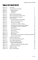
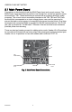
GREEN CLASS NET METER 2.0 INTERNAL ELECTRONIC ASSEMBLIES The unit is comprised of two major subassembly boards, the main power board and the display board. Both circuit boards are mounted inside a NEMA 4X enclosure. MAIN POWER BOARD DISPLAY BOARD M33270 Fig. 1. Internal Electronic Assemblies.
GREEN CLASS NET METER 2.1 Main Power Board Connections to this board include the MAIN Power Input and current sensors. The MAIN Power Input terminals are positions one through four on the four position screw terminal block, TB1. These terminals are covered with a protective shield for safety purposes. The current sensor assemblies interface to the TB2, TB3 and TB4.
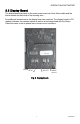
GREEN CLASS NET METER 2.2 Display Board The display board connects to the main power board via a flex ribbon cable and the board mounts on the inside of the housing door. No additional connections to the display board are required. The display board’s LCD readout indicates the metered values as well as errors associated with the Green Class Net meter, such as phase loss or sensor error conditions. DOWN UP SELECT MENU M33279 Fig. 3. Display Board.
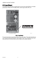
GREEN CLASS NET METER 2.3 Input Board The Green Class Net meter is supplied with an input board which allows it to accept pulses (dry contact) from third party meters, such as gas, water, BTU, etc. + INP1 + INP2 + OUT1 + OUT2 INPUT TERMINALS CL5000 METER INPUT BOARD M33272 Fig. 4. Input Board. The input terminals are used by the Green Class Net meter. The output terminals are not. Connect metering devices with “dry contacts” only.
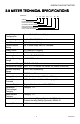
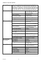
GREEN CLASS NET METER 3.0 METER TECHNICAL SPECIFICATIONS EXAMPLE: E 50 208 400 R 05 E-MON CLASS 5000 METER INPUT VOLTAGE (208V) CURRENT RATING (400A) ENCLOSURE (4X) EZ7/BACnet IP/NO MODEM SPLIT CORE SENSORS KIT M33273 Input Voltage Configuration 3-wire (Delta) Or 4-wire (Wye) Mains Voltage Input Up To 480 VAC RMS Available Input Power 6 VA Maximum Rating Current Sensor Rating Up To 3200 Amps RMS AC Available Power Factor 0.
GREEN CLASS NET METER Standard Ranges 4-Wire Wye, 120/208 VAC: 100, 200, 400, 800,1600,3200 Amp 2 Phase, 120/240 VAC: 100, 200, 400, 800,1600,3200 Amp 4-Wire Wye, 277/480 VAC: 100, 200, 400, 800,1600,3200 Amp 3-Wire Delta, 220/240 VAC: 100, 200,400,800,1600,3200 Amp 3-Wire Delta, 480 VAC: 100, 200, 400, 800,1600,3200 Amp Modem Interface Cable: UL-listed Telephone Cord, 6-cond. 300 VAC, Stranded Cond. 22-26 AWG.
GREEN CLASS NET METER 4.0 SAFETY LABEL DEFINITIONS AND INFORMATION The Green Class Net meter may contain one or more of the following labels. Operator(s) should familiarize themselves with the meaning of each label to minimize risk. The presence of this label is a cautionary indicator identifying a danger risk. The manual should be consulted prior to proceeding. The presence of this label indicates an electrical shock hazard exists in the location or area where the label is placed.
GREEN CLASS NET METER 5.0 PRECAUTIONARY AND SAFETY INFORMATION CAUTION Internal circuit card components are extremely sensitive to electrostatic discharge. Be careful not to touch internal circuitry prior to discharging any static buildup on your person. To discharge yourself, touch a grounded metal object such as conduit or an earth-grounded metal enclosure. WARNING High voltages present on main PCB terminal block TB1 screw terminals. Risk of serious injury and/or electrical shock exists.
GREEN CLASS NET METER 6.0 METER INSTALLATION 6.1 Mounting the Green Class Net Meter Use appropriately sized mounting hardware to fasten the meter enclosure to the selected mounting surface. The four housing mounting holes are centered 6.75” H x 4” W. NOTE: Units housed in UL Type 1 enclosures must only be installed in indoor environments, where they will not be affected by the elements. 6.2 Main Power Board Connections 1. 2.
GREEN CLASS NET METER a. Connect the NEUTRAL wire to the appropriate terminal block position. Fig. 5. Terminal Block TB1. NOTE: For 3-wire delta-type meters, Do NOT connect the NEUTRAL wire. Remove the terminal block screw for this position. b. Earth Ground Connect the Earth Ground to the PCB mounting screw in the lower right corner. c.
GREEN CLASS NET METER f. Verify the voltage readings on Screen 5 using an AC voltmeter. Typical readings shown below are measured phase to neutral for 4 wire and phase to phase for 3 wire. Readings should be +/- 10% of nominal.
GREEN CLASS NET METER 6.4 Current Sensor Installation & Wiring Once the AC voltages have been confirmed to be within acceptable limits, you are ready to install the current sensors. TB1, positions 5 and 6 are the inputs for Phase A, TB1 positions 7 and 8 are the inputs for Phase B and TB1 positions 9 and 10 are the Phase C inputs. The Green Class Net meter can be used with two types of current sensors: 1. 2. Split-core current sensor.
GREEN CLASS NET METER LOAD SOURCE M33213 Fig. 7. Install of a Split Core Sensor. IMPORTANT: When looking from the source side of the conductor(s) being monitored, you should see the arrow on the current sensor assembly. The arrow should be pointing in a clockwise direction around the conductor(s) being monitored. If the arrow is not positioned on the source side, inaccurate readings will result. 6.4.
GREEN CLASS NET METER 6.4.2 Current Sensor Wiring (continued) If the meter displays an error message (see below), remove the wires from terminals 5 and 6 and install them on terminals 7 and 8 (Phase B). if an error message occurs with the sensor attached to terminals 7 and 8, try again on terminals 9 and 10 (Phase C). The “CT Error: * “message will disappear when the current sensor is connected to the correct terminals (phase).
GREEN CLASS NET METER 6.5 Main Power & Current Sensor Wiring Diagram LINE VOLTAGE N ∅A ∅B ∅C 3-PHASE INSTALLATION DIAGRAM CURRENT SENSORS ∅C ∅A ∅B W B W B W B NOTES: LINE VOLTAGE CONNECTIONS: #14-22 AWG SENSOR CONNECTIONS: W = WHITE LEAD B = BLACK LEAD 1 1 1 ∅A NEUTRAL NOT USED IN DELTA SYSTEM. ∅B LITTLEFUSE PART NUMBER KLDR 100. 1 ∅C 1/10A 600 VAC INLINE FUSE PER CONDUCTOR. LITTLEFUSE PART NUMBER KLDR, 100. LOAD N SOURCE M33194 Fig. 8. Current Sensor Wiring Diagram. 6.
GREEN CLASS NET METER 6.6.2 Current Sensor Diagnostics The load current must be at least 1% of the meter’s rated load in order to use the diagnostic function. Current sensor diagnostics can detect: 1. 2. 3. Reversed current sensors Incorrect phase correspondence Unusually low power factor (0.642 or lower) CT Error: (ABC) is used to detect the swapping of current sensor phases. This message could (in some rare cases) indicate a low (<65%) power factor condition.
GREEN CLASS NET METER 6.7 RS-485 Wiring RS-485 communication allows a computer or modem to communicate with one or more Green Class Net meters. You can connect as many as 52 meters along a 4000foot RS-485 cable run. There are four communication protocols available through the Green Class Net RS485 connection. They are EZ7, Modbus RTU, BACnet MS/TP, and Lonworks FT-10. The protocol is chosen when ordering the Green Class Net meter. A second protocol is available through the Ethernet port.
GREEN CLASS NET METER 6.7 RS-485 Wiring (continued) After performing these steps, all of the meters will be connected in a daisy chain configuration. This network of meters can then be connected to the RS-485 network and communication can be established. Internal Modem An optional internal modem inside one meter will communicate with the others via the RS-485 network. Simply connect one of the two telephone jacks on the modem to the telephone line to complete the installation.
GREEN CLASS NET METER 6.8 RS-232 Communications 6.8.1 Hardwired System using the RS-232 Communication Key The RS-232 communications key allows you to connect Green Class Net meters to a personal computer that has the E-Mon Energy™ software installed. The computer communicates with the meters through the RS-232 key. The RS-232 key must be located within 15 feet of the host computer.
GREEN CLASS NET METER 3. Connect the provided AC adapter into the rear panel input on the RS- 232 key. Plug the adapter into a 120VAC outlet. On the front panel of the RS-232 key, two LEDs (POWER ON and AC ON) will light up. NOTE: When the E-Mon Energy™ software is accessed on the computer, a third LED (RS232 READY) will turn on. This indicator will light up as soon as the E-Mon Energy software is booted up and the correct COM port is set up via the settings provided in the software’s Locations menu. 6.
GREEN CLASS NET METER 6.9 Modem Wiring RS-232 SERIAL PORT COM1 THROUGH COM3 MAXIMUM 15 FEET CHANNEL 1 LOCAL MODEM ~ ~ PC OR WINDOWS COMPATIBLE TELEPHONE LINK UP TO 4000 FEET TOTAL ~ UP TO 52 ~ GREEN CLASS NET METERS PER CHANNEL RS-232 KEY RM CHANNEL 2 AC ADAPTER CHANNEL 3 UP TO 4000 FEET TOTAL ~ UP TO 52 ~ GREEN CLASS NET METERS PER CHANNEL M33424 Fig. 12. Modem Configuration. 6.9.
GREEN CLASS NET METER 6.9.2 External Modem 1. 2. 3. 4. 5. All meters should be connected to the RS-232 key as described in 6.8.2. 2. DISCONNECT POWER TO THE RS-232 KEY. Remove the cover by removing the 2 screws from the bottom of the enclosure. On the circuit board, locate the blue jumpers J7 (MODEM) and J8 (ex-MODEM). If these jumpers are set in the DIRECT position, you must move the jumpers so they are set in the MODEM position. Re place the cover and secure the enclosure.
GREEN CLASS NET METER 6.9.3 Baud Rate Selection The communication baud rate is selected by means of a jumper on the circuit board. There are four (4) selections: 19200 (factory default), 19200, 38400, and 76800. 1. 2. 3. 4. 5. Select 9600 when using the Green Class Net meter with a modem. The baud rate on the meter must always match the baud rate selected in the EMon Energy software; otherwise, communications will not work. After a baud rate change, press CPU Reset to register the change.
GREEN CLASS NET METER 6.10 Modbus RTU Wiring The Green Class Net Modbus meter communicates with building automation equipment over a 2-wire (3-conductor) RS-485 network using Modbus RTU protocol. The meters are networked in a daisy-chain configuration (Section 6.7) with BELDEN 1120A cable or equivalent. The cable rating of 600V allows the RS-485 network to be connected to 480-volt meters. Up to 52 meters can be installed on a network string.
GREEN CLASS NET METER 6.12 Connecting Green Class Net Meters to the USB Key using RS485 The USB Key plugs into the PC’s USB port and provides a termination point for the RS485 wiring from the meters. Up to 52 meters can be “Daisy chained” with up to 4000 feet total RS485 wiring. The USB Key is labeled for “plus (+)”, “minus (-)“, and ground and the wiring must match the same positions on the meters. If more than 52 meters are to be monitored, additional USB Keys can be utilized to connect them to the PC.
GREEN CLASS NET METER 6.13 Ethernet Communications Ethernet/IP communications connections are provided through an RJ-45 connector(J8) in the lower right corner of the main power board. This port can be connected directly to a network port of a PC using a Cat. 5e crossover cable. Two LEDs are provided directly above the connector. The LINK LED is yellow and when lit, indicates ethernet connectivity. The ACT led is green and when lit, indicates communication activity.
GREEN CLASS NET METER 6.12 Ethernet Communications (continued) EMS OR CONTROL UNIT WITH MODBUS COMMUNICATION M32786 RS-485 DAISY CHAIN (SECTION 5.7) ETHERNET NETWORK M32787 Fig. 16. Ethernet/IP Communications.
GREEN CLASS NET METER 7.0 MULTIPLE-LOAD MONITORING The E-Mon D-Mon Green Class Net meter provides extreme flexibility by allowing additional sets of current sensors to be used in parallel so multiple load locations can be monitored by one meter. This feature allows a totalized display readout from two or more load circuits. You may use parallel sensors to monitor specific breakers from one panel, specific breakers from more than one panel, two or more complete panels, etc.
GREEN CLASS NET METER NOTE: One set of current sensors equates to three sensors, one per phase. The multiplier only applies when extra sets of current sensors are installed on one meter. If you are using only one set of three current sensors, the multiplier is not required. LINE VOLTAGE ØAØB ØC N LOAD LOAD SOURCE LOAD A SOURCE LOAD B CURRENT SENSORS ØA ØB ØC WB WB WB ØA ØB ØC N ØA ØB ØC N M31603 Fig. 17. Multiple-load Wiring Diagram. 8.
GREEN CLASS NET METER 9.0 LITHIUM BATTERY REPLACEMENT INSTRUCTIONS The Green Class Net kWh/Demand meter has a Lithium Battery Cell, which is used to retain the contents of SRAM and the RTC during power outages. The battery has a life expectancy of greater than 5 years. Nominal Working Voltage 3 Vdc Output Nominal Current Capacity 225 mAHr Cell Chemical Manganese Dioxide Lithium Operating Temperature Range -30 to +60 Degrees Celsius Manufacturer Panasonic Manufacturer’s Part Number CR2032 Fig.
GREEN CLASS NET METER The battery cell is mounted in a coin cell on the upper right side of the main power board. Replace the battery if the low battery warning is on display. + – BATTERY M33278 Fig. 19. Lithium Battery Cell. Use the following procedure to replace the battery cell STEP 1: Disconnect power from the meter at the unit external circuit breaker. STEP 2: Remove the battery from its holder and place on a non-conductive surface. STEP 3: Install new battery into the battery holder.
GREEN CLASS NET METER 10.0 GREEN CLASS NET METER FEATURES 10.1 Display Board Push Buttons DOWN UP SELECT MENU M33279 Fig. 20. Push Buttons.
GREEN CLASS NET METER 10.1 Display Board Push Buttons (continued) To access any of these items press the MENU button. The list will be displayed and an arrow will appear to the left of LOAD CONTROL. To scroll down the list press the MENU button until the desired item is indicated by the arrow. Then push the SELECT button to enter the configuration screen for that item. The UP and DOWN buttons can then be used to change the configuration field that is flashing.
GREEN CLASS NET METER COST/CO2 Settings To SET THE COST / CO2, press the MENU button until “COST / CO2” is indicated by the arrow on the display. Press the SELECT button. Set the COST/KWH and CO2/KWH. Display Hold Feature You can “lock” the scrolling display so that it will stay locked on any one of the six screens. On the inside of the door, locate the 4 buttons at the top of the Display Board: Down, Up, Select and Menu. (These buttons are illustrated on page 26.
GREEN CLASS NET METER 10.2 Reading the Green Class Net Meter Display The Green Class Net meter features nine different displays showing information in 5 second scrolling intervals.
GREEN CLASS NET METER 11.0 FREQUENTLY ASKED QUESTIONS Q. When providing line voltage to the meter, can I tap off of the same breaker I am monitoring? A. Yes, the voltage can be pulled from the same breaker being monitored. Q. Can the meter’s line voltage wires be run in the same conduit as the sensor leads? A. Yes. There will be no effect if the sensor leads and line voltage wires are run in the same conduit. Q. Can the meter’s communication wires and line voltage be run in the same conduit? A.
GREEN CLASS NET METER Q. The load I need to monitor has parallel feeds. How do I install the current sensors for this application? A. There are two ways you can monitor parallel feeds. The easiest and preferred method is to clamp the sensors around all feed wires for each phase. The second way to monitor parallel feeds is to clamp the sensor around one of the feed wires for each phase. When you read the Green Class Net meter, the final reading must be multiplied by the number of feed wires for each phase.
GREEN CLASS NET METER 12.0 MODBUS POINT MAPS Modbus Integer Registers: Address Reg Description Units CL5000 40001* 2 Energy delivered kWh Pulse R/W 40003 2 Energy received kWh Pulse R/W 40005 2 Reactive energy delivered kVARh Pulse R/W 40007 2 Reactive energy received kVARh Pulse R/W * To clear single meter kWh/kVARh, set multiple points at 40001 for 8 points with data set to 0000 0000 0000 0000 0000 0000 0000 0000. Jumper J6 must be closed.
GREEN CLASS NET METER Modbus Float Registers (continued): 41047 2 Power factor, phase A % PF R 41049 2 Power factor, phase B % PF R 41051 2 Power factor, phase C % PF R 41053 2 Current, phase A Amps R 41055 2 Current, phase B Amps R 41057 2 Current, phase C Amps R 41059 2 Voltage, line to neutral, phase A-N Volts-N R 41061 2 Voltage, line to neutral, phase B-N Volts-N R 41063 2 Voltage, line to neutral, phase C-N Volts-N R 41065 2 Voltage, line to line, phase
GREEN CLASS NET METER BACnet Object Descriptors (continued): 5 Analog Input Real power kW 6 Analog Input Reactive power kVARh Present Value R 7 Analog Input Apparent power kVARh Present Value R 8 Analog Input Power factor % PF Present Value R 9 Analog Input Current total Amps Present Value R 10 Analog Input Current average Amps Present Value R 11 Analog Input Voltage line-neutral Volts-N Present Value R 12 Analog Input Voltage line-line Volts-L Present Value R 13 Analog Input Freque
GREEN CLASS NET METER BACnet Object Descriptors (continued): 27 Analog Input Current phase A Amps Present Value R 28 Analog Input Current phase B Amps Present Value R 29 Analog Input Current phase C Amps Present Value R 30 Analog Input Voltage line-neutral phase A-N Volts-N Present Value R 31 Analog Input Voltage line-neutral phase B-N Volts-N Present Value R 32 Analog Input Voltage line-neutral phase C-N Volts-N Present Value R 33 Analog Input Voltage line-line phase A-B Volts-L Present Value R
GREEN CLASS NET METER Lonworks SNVT Types Point Map (continued): nvoKVarh_Rec SNVT_count_inc_f Reactive energy received kVARh R nvoReal_Pwr SNVT_count_inc_f Real power kW nvoReact_Pwr SNVT_count_inc_f Reactive power kVARh R nvoAppar_Pwr SNVT_count_inc_f Apparent power kVARh R nvoPwr_Fact SNVT_pwr_fact_f Power factor % PF R R nvoCurrent_Total SNVT_amp_f Current total Amps R nvoCurrent_Avg SNVT_amp_f Current average Amps R nvoVolt_LN SNVT_volt_f Voltage line-neutral Volts-N R
GREEN CLASS NET METER Lonworks SNVT Types Point Map (continued): nvoVolt_LN_PhA_N SNVT_volt_f Voltage, line to neutral, phase A-N Volts-N R nvoVolt_LN_PhB_N SNVT_volt_f Voltage, line to neutral, phase B-N Volts-N R nvoVolt_LN_PhC_N SNVT_volt_f Voltage, line to neutral, phase C-N Volts-N R nvoVolt_LL_PhA_B Voltage, line to line, phase A-B Volts-L R SNVT_volt_f 47 62-0416-01
GREEN CLASS NET METER 13.0 METER LIMITED WARRANTY Subject to the exclusions listed below, E-Mon will either repair or replace (at its option) any product that it manufactures and which contains a defect in material or workmanship. The following exclusions apply: 1. 2. 3. 4. 5. 6. 7. 8. This Limited Warranty is only effective for a period of (5) five years following the date of manufacture when installed in accordance with manufacturer’s instructions by qualified personnel.