Class 3200 Meter ADVANCED KWH/DEMAND METER INSTALLATION INSTRUCTIONS E-Mon 850 Town Center Drive Langhorne, PA 19047 (800) 334-3666 www.emon.com info@emon.
CLASS 3200 METER Dear Valued Customer, We are pleased that you chose to buy one of our products, and want you to be just as pleased with owning it. Before installing your new E-Mon product, please read the information on the following pages carefully. We believe that you will find the E-Mon D-Mon meters easy to install and to use for monitoring and evaluating your electrical usage.
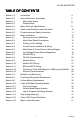
CLASS 3200 METER TABLE OF CONTENTS Section 1.0 Introduction 4 Section 2.0 Internal Electronic Assemblies 6 Section 2.1 Main Power Board 6 Section 2.2 Display Board 7 Section 3.0 Meter Technical Specifications 8 Section 4.0 Safety Label Definitions and Information 10 Section 5.0 Precautionary and Safety Information 11 Section 6.0 Meter Installation 12 Section 6.1 Mounting the Class 3200 Meter 12 Section 6.2 Main Power Board Connections 12 Section 6.
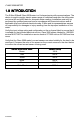
CLASS 3200 METER 1.0 INTRODUCTION The E-Mon D-Mon® Class 3200 meter is a 3-element meter with communications. The device is used to monitor electric power usage of individual loads after the utility meter and store kW and kVAR data for automatic meter reading. Installation must only be performed by qualified personnel and in accordance with these instructions and all applicable local and national electrical codes.
CLASS 3200 METER CAUTION Internal circuit components are extremely sensitive to electrostatic discharge. Prior to handling or touching internal circuitry, discharge any static buildup on your person. To discharge yourself, touch a grounded metal object such as conduit or an earth-grounded enclosure.
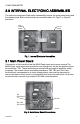
CLASS 3200 METER 2.0 INTERNAL ELECTRONIC ASSEMBLIES The units are comprised of two major subassembly boards, the main power board and the display board. Both circuit boards are mounted inside a UL Type 1 or Type 4X enclosure. MAIN POWER BOARD DISPLAY BOARD M33307 Fig. 1. Internal Electronic Assemblies. 2.1 Main Power Board Connections to this board include the MAIN Power Input and current sensors.
CLASS 3200 METER 2.2 Display Board The display board connects to the main power board via a flex ribbon cable and the board mounts on the inside of the housing door. The Class 3200 meter features a 4-line LCD display that indicates multiple meter data points. DOWN UP SELECT MENU M33279 Fig. 3. Display Board.
CLASS 3200 METER 3.
CLASS 3200 METER 3.
CLASS 3200 METER 4.0 SAFETY LABEL DEFINITIONS AND INFORMATION The 3200 meter may contain one or more of the following labels. Operator(s) should familiarize themselves with the meaning of each label to minimize risk. The presence of this label is a cautionary indicator identifying a danger risk. The manual should be consulted prior to proceeding. The presence of this label indicates an electrical shock hazard exists in the location or area where the label is placed.
CLASS 3200 METER 5.0 PRECAUTIONARY AND SAFETY INFORMATION CAUTION Internal circuit card components are extremely sensitive to electrostatic discharge. Be careful not to touch internal circuitry prior to discharging any static buildup on your person. To discharge yourself, touch a grounded metal object such as conduit or an earth-grounded metal enclosure. WARNING High voltages present on main PCB terminal block TB1 screw terminals. Risk of serious injury and/or electrical shock exists.
CLASS 3200 METER 6.0 METER INSTALLATION 6.1 Mounting the Class 3200 Meter Use appropriately sized mounting hardware to fasten the Class 3200 enclosure to the selected mounting surface. The four housing mounting holes are centered 6.75” H x 4” W. When the meter is provided in the 4X rated enclosure, the hub must be mounted to the conduit first before connecting it to the enclosure.
CLASS 3200 METER 6.2 Main Power Board Connections (continued) 3. Wire Entry: One 3/4” conduit opening is located on the bottom of the CL3200 enclosures. This opening is used for bringing in MAINS power and for current sensor wiring. One 1/2” conduit opening on the top of the metal enclosure CL3200 can be utilized as an interface for the low- voltage signals, pulse input, or RS-485 communications wiring to the unit.
CLASS 3200 METER 6.2 Main Power Board Connections (continued) D. Connect the three AC main power wires (Phases A, B and C) to their respective positions as labeled on terminal block TB1. After all conductors are connected to each of their respective terminal block positions and tightened to 7 in-lb, verify that each terminal block screw is securely fastened by gently tugging on each conductor. Verify that no conductor wires are frayed or shorting to adjacent terminal block positions. E.
CLASS 3200 METER 6.3 Phasing of Line Voltage The 3-phase AC power input must be in proper phase sequence. If the sequence is incorrect or a phase is missing, there will be a message on the meter’s display: “PH Sequence Error” or “PH Missing:. (Refer to the section on Line Voltage Diagnostics if this message is present.) When the line voltage is connected correctly, the meter’s display will be blank (no message.) Wait for the 4-line meter display to scroll to the voltage display.
CLASS 3200 METER 6.4 Current Sensor Installation & Wiring Once the AC voltages have been confirmed to be within acceptable limits, you are ready to install the current sensors. TB2 is the input for Phase A, TB3 is the input for Phase B and TB4 is the Phase C input. The Class 3200 meter can be used with two types of current sensors: 1. 2. Split-core current sensor. This sensor opens so that it can be attached around the circuit being monitored without interrupting power. Solid-core current sensor.
CLASS 3200 METER 6.4.1 Current Sensor Wiring Once the current sensors are installed onto their appropriate phase conductors, you can begin terminating the current sensors onto the Class 3200 main board. The current sensors can be extended up to 500 feet for remote monitoring applications. To extend the length of the wires, use #22 AWG twisted-pair wire with one white and one black wire. The easiest way to connect the current sensors is to use the meter’s built-in current sensor diagnostics.
CLASS 3200 METER 6.5 Main Power & Current Sensor Wiring Diagram LINE VOLTAGE N 3-PHASE, 4-WIRE INSTALLATION DIAGRAM PE CURRENT SENSORS C WB WB WB NOTES: LINE VOLTAGE CONNECTIONS: #14-12 AWG SENSOR CONNECTIONS: B = BLACK LEAD W = WHITE LEAD 1 1 1 NEUTRAL NOT USED IN DELTA SYSTEM. REMOVE NEUTRAL TERMINAL BLOCK SCREW FOR DELTA SYSTEMS. 1 1/10A 600 VAC INLINE FUSE PER CONDUCTOR. LITTLEFUSE PART NUMBER KLDR.100. LOAD SOURCE N M33185 Fig. 8. 3-phase- 4 Wire Installation Diagram 6.
CLASS 3200 METER 6.6.2 Current Sensor Diagnostics The load current must be at least 1% of the meter’s rated load in order to use the diagnostic function. Current sensor diagnostics can detect: 1. 2. 3. Reversed current sensors Incorrect phase correspondence Unusually low power factor (0.642 or lower) CT Error: (ABC) is used to detect the swapping of current sensor phases. This message could (in some rare cases) indicate a low (<65%) power factor condition.
CLASS 3200 METER 6.7 RS-485 Wiring (continued) * An alternate version of firmware is available that replaces Modbus RTU with BACnet MS/TP. The meter must be ordered with this option if BACnet is desired instead of Modbus. There are two connection methods, daisy-chain and wire terminal, for RS-485 communications. Daisy-Chain Method This is the simplest method for connecting meters together. M32776 Fig. 9. Daisy-chain Configuration. 1. 2. 3. 4.
CLASS 3200 METER 6.7 RS-485 Wiring (continued) 6.7.1 RS-485 Bias Resistors When interfacing the Class 3200 meter to certain RS-485 communication equipment, it may be necessary to add bias resistance to the circuit. If this is required, there is a 2position DIP switch on the meter’s door mounted (display) circuit board. With both positions in the “ON” position, bias resistance is added to the RS-485 circuit. When both positions are in the “OFF” position, no bias is added to the RS-485 circuit. Fig. 11.
CLASS 3200 METER 6.8 RS-232 Communications 6.8.1 Hardwired System using the RS-232 Communication Key The RS-232 communications key allows you to connect Class 3200 meters to a personal computer that has the E-Mon Energy™ software installed. The computer communicates with the meters through the RS-232 key. The RS-232 key must be located within 15 feet of the host computer.
CLASS 3200 METER 6.8.2 Connecting the RS-232 Key to the Computer (continued) 3. Connect the provided AC adapter into the rear panel input on the RS- 232 key. Plug the adapter into a 120VAC outlet. On the front panel of the RS-232 key, two LEDs (POWER ON and AC ON) will light up. NOTE: When the E-Mon Energy™ software is accessed on the computer, a third LED (RS232 READY) will turn on.
CLASS 3200 METER 6.9 Modem Wiring RS-232 SERIAL PORT COM1 THROUGH COM3 MAXIMUM 15 FEET CHANNEL 1 LOCAL MODEM ~ ~ PC OR WINDOWS COMPATIBLE TELEPHONE LINK UP TO 4000 FEET TOTAL ~ UP TO 52 ~ CLASS 3200 METERS PER CHANNEL RS-232 KEY RM CHANNEL 2 AC ADAPTER CHANNEL 3 UP TO 4000 FEET TOTAL ~ UP TO 52 ~ CLASS 3200 METERS PER CHANNEL M33310 Fig. 14. Modem Configuration.
CLASS 3200 METER 6.9.1 Modem (RS-232 KEY RM) The RS-232 key with modem connects the entire RS-485 network of Class 3200 meters to a telephone line. ** Refer to Section 6.7 for RS-485 network connections. On the back panel of the RS-232 key/modem, the left jack (RS232) is not used in most cases since there is no local host computer. The two jacks at the top center of the rear panel on the RS-232 key/modem are for connecting the phone line. Connect either one of these two jacks to the telephone line.
CLASS 3200 METER 6.9.2 External Modem 1. 2. 3. 4. 5. All meters should be connected to the RS-232 key as described in 6.8.2. DISCONNECT POWER TO THE RS-232 KEY. Remove the cover by removing the 2 screws from the bottom of the enclosure. On the circuit board, locate the blue jumpers J7 (MODEM) and J8 (ex-MODEM). If these jumpers are set in the DIRECT position, you must move the jumpers so they are set in the MODEM position. Replace the cover and secure the enclosure.
CLASS 3200 METER 6.10 Modbus RTU Wiring The Class 3200 Modbus option meter communicates with building automation equipment over a 2-wire (3-conductor) RS-485 network using Modbus RTU protocol. The meters are networked in a daisy-chain configuration with BELDEN 1120A cable or equivalent required. The cable rating of 600V allows the RS-485 network to be connected to 480-volt meters. Up to 52 meters can be installed on a network string.
CLASS 3200 METER 6.11 BACnet MS/TP Wiring BACnet MS/TP wiring is the same as Modbus and EZ7 wiring. See Sections 10 and 11 for instructions on changing I.D. and IP addresses. 6.12 Connecting Class 3200 Meters to USB Key using RS485 The USB Key plugs into the PC’s USB port and provides a termination point for the RS485 wiring from the meters. Up to 52 meters can be “Daisy chained” with up to 4000 feet total RS485 wiring.
6.13 Ethernet Communications Ethernet communications connections are available through an optional EKM-E key, which converts the meter’s RS-485 output to an ethernet connection. The key provides data only with the EZ-7 protocol and is not designed to support Modbus or BACnet. NOTE: The meter is not designed to connect directly through an Ethernet connection, but must utilize an appropriate RS485/Ethernet converter module/ modem.
7.0 MULTIPLE-LOAD MONITORING The E-Mon D-Mon Class 3200 meter provides extreme flexibility by allowing additional sets of current sensors to be used in parallel so multiple load locations can be monitored by one meter. This feature allows a totalized display readout from two or more load circuits. You may use parallel sensors to monitor specific breakers from one panel, specific breakers from more than one panel, two or more complete panels, etc.
7.0 MULTIPLE-LOAD MONITORING (CONTINUED) NOTE: One set of current sensors equates to three sensors, one per phase. The multiplier only applies when extra sets of current sensors are installed on one meter. If you are using only one set of three current sensors, the multiplier is not required. LINE VOLTAGE ØAØB ØC N LOAD LOAD SOURCE LOAD A SOURCE LOAD B CURRENT SENSORS ØA ØB ØC WB WB WB ØA ØB ØC N ØA ØB ØC N M31603 Fig. 19. Multiple-load Wiring Diagram. 8.
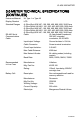
9.0 LITHIUM BATTERY REPLACEMENT The Class 3200 meter has a lithium coin cell battery, which is used to retain the contents of SRAM and the RTC during power outages. The battery’s life expectancy is greater than 5 years. Nominal Working Voltage 3 Vdc Output Nominal Current Capacity 225 mAHr Cell Chemical Manganese Dioxide Lithium Operating Temperature Range -30 to +60 Degrees Celsius Manufacturer Panasonic Manufacturer’s Part Number CR2032 Table 1. Battery specifications at 25 degrees Celsius.
9.0 LITHIUM BATTERY REPLACEMENT (CONTINUED) Use the following procedure to replace the lithium battery cell. CAUTION The battery is not completely discharged; therefore, DO NOT short the terminals on the battery with any conductive material. CAUTION Internal circuit card components are extremely sensitive to electrostatic discharge. Be careful not to touch internal circuitry prior to discharging any static buildup on your person.
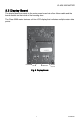
10.0 CLASS 3200 METER OPERATING MODES The E-Mon D-Mon® Class 3200 meter is used to monitor electric power usage of individual loads after the utility meter and store kW and kVAR data for automatic meter reading. Fig. 21. Class 3200 Stand Alone Meter with 4 Line Display. 10.1 Start Up Screens When the meter starts up, the screen displays firmware image type.
10.2 Normal Mode Display Screens The Class 3200 meter features seven Normal Mode Display Screens for monitoring the meter. Each screen is displayed for 5 second intervals, before scrolling onto the next screen. You can “lock” the scrolling display on any one of the seven screens. This will be explained in detail on following pages.
DOWN UP SELECT MENU M33279 Fig. 24. Push Buttons. 10.3 How to Program the Display Screens The display information can be programed using four push buttons switches. The push buttons (DOWN, UP, SELECT, MENU) are located at the bottom of the display board on the inside front door of the meter. The buttons are used to program the following: • Date & Time (This field sets the month, day, year, and time.) • Device ID (This field changes the default setting, which is 1A for EZ7 and 1 for ModBus.
10.3.1 Date & Time To change the date and time, complete the following steps: 1. 2. Press the MENU button. The following screen will appear: Date & Time Device ID Reset KW/KWH Read Exit 3. Press the SELECT button. The date and time screen will appear, and the 2 digit month will be blinking. DATE: 02-16-2012 TIME: 01:57:36 4. 5. Use UP or DOWN button to make changes, press SEL button to advance to the next field. Press MENU button to return to main menu.
10.3.2 Device I.D. To change Device I.D., complete the following steps: 1. 2. Press the MENU button. The following screen will appear: Date & Time Device ID Reset KW/KWH Read Exit 3. Use the UP and DOWN buttons to select the Device ID line. Press the SELECT button. The Device I.D. screen will appear. EZ7 ID: MODBUS ID: 4. . 1A 2 Use UP or DOWN button to make changes, press SEL button to advance to the next field. Press MENU button to return to main menu. Save Change? Y 5.
10.3.3 Peak Demand Reset To reset the recorded peak kW demand, complete the following steps: 1. Press the MENU button until “Reset kW/kWh Read” is indicated by the arrow on the display. Date & Time Device ID Reset KW/KWH Read Exit 2. Press the SELECT button. The following screen will appear on the display. Reset kW only? N Reset all? N 3. Press the UP button to change the N to a Y after “Reset kW only?”. 4.
10.3.4 Display Hold Feature You can “lock” the scrolling display so that it will stay locked on any one of the seven screens. To stop the display from scrolling, complete the following steps: 1. Press the UP and DOWN buttons to choose which of the six screens you would like to display. 2. Press the Select button. At the top of the display, you will see the message HOLD1. This will lock the display for 1 HOUR. NOTE: The display hold feature has different selectable time periods. 3.
11.0 HIGH VOLTAGE METERING kWh Meter Installation Instructions for Use with E-MON Meters in High Voltage Applications The E-MON model # E34-12025HV kWh meter is designed to be used for monitoring high voltage (2400, 4160, 13200, etc) circuits, either “stand alone” or in an AMR application. This meter is intended to be used with the appropriate high voltage Potential Transformers (PTs) and Current Transformers CTs) supplied by others.
M34227 Fig. 25. High Voltage CT’s. M34228 Fig. 26. Wiring Diagram For 3-wire High Voltage Circuits.
This special high voltage meter installation shows the correct wiring procedure for 4wire high voltage circuits. In this application, the 3 element meter connection is used on the secondary circuits of the user supplied high voltage PTs and CTs. The E-MON meter used in this application is the model E34-12025HV kWh meter. Installation of these meters requires the use of three (3) current sensors mounted on the secondaries of the high voltage Current Transformers. See the drawing above for proper wiring.
12.
ModBus Customer Point Map: CL3200 Address Registers Format Description Units CL 3200 41033 2 Float Real power, phase C kW R 41035 2 Float Reactive power, phase A kVAR R 41037 2 Float Reactive power, phase B kVAR R 41039 2 Float Reactive power, phase C kVAR R 41041 2 Float Apparent power, phase A kVA R 41043 2 Float Apparent power, phase B kVA R 41045 2 Float Apparent power, phase C kVA R 41047 2 Float Power factor, phase A % PF R 41049 2 Float Power fac
ModBus Customer Point Map: CL3200 Address Registers Format Description Units CL 3200 41075 2 Float Phase angle, phase C Degree R 410832 2 Float External Input 1 Pulse R/W 410852 2 Float External Input 2 Pulse R/W 440013 6 Custom Interval Day Block 440074 1 per interval Integer Interval Data 455015 2 per day Custom Interval Data Headers R 460256 8 Custom RTC Date/Time R/W 460497 8 Custom EZ7 ID, ModBus ID, Serial Number R/W 46057 8 Custom Recorder Info.
BACnet Object Descriptors: CL3200 Instance ID BACnet Object Description Units BACnet Property CL 3200 11 Analog Input Energy delivered kWh Present Value R 21 Analog Input Energy received kWh Present Value R 31 Analog Input Reactive energy delivered kVARh Present Value R 41 Analog Input Reactive energy received kVARh Present Value R 5 Analog Input Real power kW Present Value R 6 Analog Input Reactive power kVAR Present Value R 7 Analog Input Apparent power kVA Present
BACnet Object Descriptors: CL3200 Instance ID BACnet Object Description Units BACnet Property CL 3200 20 Analog Input Reactive power phase C kVAR Present Value R 21 Analog Input Apparent power phase A kVA Present Value R 22 Analog Input Apparent power phase B kVA Present Value R 23 Analog Input Apparent power phase C kVA Present Value R 24 Analog Input Power factor phase A % PF Present Value R 25 Analog Input Power factor phase B % PF Present Value R 26 Analog Input Pow
BACnet Object Descriptors: CL3200 Instance ID BACnet Object Description Units BACnet Property CL 3200 39 Analog Input Reserve A No units Present Value R 40 Analog Input Reserve B No units Present Value R 41 Analog Input Reserve C No units Present Value R 422 Analog Input External Input 1 Pulse Present Value 432 Analog Input External Input 2 Pulse Present Value 1. To clear single meter kWh/kVARh, select reset kW/kWh on the display menu of the meter.
Instance ID BACnet Object BACnet Property CL3200 BACnet Device ID Device Object identifier R BACnet Device ID Device Object name R BACnet Device ID Device Object type R BACnet Device ID Device System status R/W BACnet Device ID Device Vendor name R BACnet Device ID Device Vendor Identifier R BACnet Device ID Device Model name R BACnet Device ID Device Firmware revision R BACnet Device ID Device Application software version R BACnet Device ID Device Location R/W BA
13.0 LIMITED METER WARRANTY Subject to the exclusions listed below, E-Mon will either repair or replace (at its option) any product that it manufactures and which contains a defect in material or workmanship. The following exclusions apply: 1. 2. 3. 4. 5. 6. 7. 8. This Limited Warranty is only effective for a period of (5) five years following the date of manufacture when installed in accordance with manufacturer’s instructions by qualified personnel.
E-Mon 850 Town Center Drive Langhorne, PA 19047 www.emon.com info@emon.com ® U.S. Registered Trademark © 2012 E-Mon 62-0390-02 JPG Rev.