
Manual


CLASS 2000 METER
62-0389-05 16
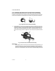
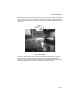
1. Disconnect the Gray current sensor plugs for current sensor B and C phase
inputs (see Fig. 10).
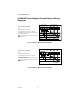
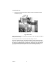
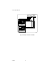
Fig. 10. Error LED
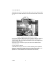
With only the A sensor wires connected to the sensor A input verify if the error LED is
clear (Green LED is off).
If Error LED is clear then the A sensor input leads polarity is correct.
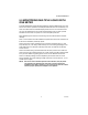
If the Error LED does not clear, then disconnect the gray plug and reverse the input
leads for A sensor by putting the white leads on the black input and the black leads on
the white input, (swapped polarity). If it clears, the “Sensor Error” then mark this pair
with a piece of masking tape as the A sensor and note polarity. Next disconnect the
gray plug for the A input. Marking them with tape as A and noting the polarity.
POWER LED
PULSE LED
ERROR LED
M34955