Class 2000 Meter KWH & KWH/DEMAND METER INSTALLATION INSTRUCTIONS E-Mon 850 Town Center Drive Langhome, PA 19047 (800)334-3666 www.emon.
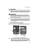
CLASS 2000 METER Dear Valued Customer, We are pleased that you chose to buy one of our products, and want you to be just as pleased with owning it. Before installing your new E-Mon product, please read the information on the following pages carefully. We believe that you will find the E-Mon D-Mon meters easy to install and to use for monitoring and evaluating your electrical usage.
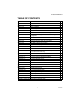
CLASS 2000 METER TABLE OF CONTENTS Section 1.0 Pre-Installation Information 4 Section 2.0 Safety Label Definitions and Information 6 Section 3.0 Precautionary and Safety Information 7 Section 4.0 Meter Installation 8 Section 4.1 Mounting the Meter 8 Section 4.2 Main Power Board Connections 8 Section 4.3 Current Sensor Installation & Wiring 11 Section 4.4 MAINS Line Voltage & Current Sensor Wiring Diagrams 14 Section 4.5 Installation Overview 15 Section 4.
CLASS 2000 METER 1.0 PRE-INSTALLATION INFORMATION The E-Mon D-Mon® Class 2000 kWh/Demand meter is a 3-element meter used to monitor electric power usage of individual loads after the utility meter. Installation must only be performed by qualified personnel and in accordance with these instructions and all applicable local and national electrical codes. E-Mon or its representatives assume no responsibility for damages or injury resulting from the improper installation of this meter.
CLASS 2000 METER CAUTION Internal circuit card components are extremely sensitive to electrostatic discharge. Prior to handling or touching internal circuitry, discharge any static buildup on your person. To discharge yourself, touch a grounded metal object such as conduit or an earth grounded metal enclosure.
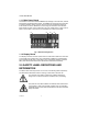
CLASS 2000 METER 1.1.1 Main Power Board Connections to this board include the MAINS Input Voltage, Current Sensors, external IDR interface and Isolated Pulse Output. The MAINS input terminals are covered with a protective shield for safety purposes. The current sensor assemblies interface to three header connectors, labeled A, B, and C along with conductor color indication.
CLASS 2000 METER 3.0 PRECAUTIONARY AND SAFETY INFORMATION CAUTION Internal circuit card components are extremely sensitive to electrostatic discharge. Be careful not to touch internal circuitry prior to discharging any static buildup on your person. To discharge yourself, touch a grounded metal object such as conduit or an earth-grounded metal enclosure. WARNING High voltages present on main PCB terminal block TB1 screw terminals. Risk of serious injury and/or electrical shock exists.
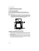
CLASS 2000 METER 4.0 METER INSTALLATION 4.1 Mounting the Meter Using the appropriate sized mounting hardware, fasten the Class 2000 meter enclosure to the selected mounting surface. The four mounting holes are centered 6.75” H x 4” W. The mounting hole spacing is identical for either the UL Type 1 or NEMA 4X enclosure. NOTE: Only the NEMA 4X plastic enclosed unit is suitable for outdoor environmental conditions.
CLASS 2000 METER WARNING Failure to attach the protective earth ground wire securely to the enclosure creates a potential shock hazard. Do not operate the Class 2000 meter without a protective earth ground connection securely installed. 3. 4. Wire Entry. a. Two openings exist on the unit enclosure, one for 1/2” conduit and one for 3/ 4” conduit. The 3/4” conduit opening located on the bottom of the enclosure is used to bring in MAINS Power (voltage lines to power meter) and current sensor wiring.
CLASS 2000 METER d. Connect the AC mains power wires (Phase A, Phase B and Phase C) to their respective positions as labeled on terminal block.Tighten the screws to 7 inlb of torque. e. After all conductors are connected to their respective terminal block positions and tightened down, verify that each terminal block screw is securely fastened by gently tugging on each conductor. Verify no conductor wires are frayed or are shorting to adjacent terminal block positions. 5. 6. 7.
CLASS 2000 METER 4.3 Current Sensor Installation & Wiring Once the AC voltages have been confirmed to be within acceptable limits, you are ready to install the current sensors. The MAIN power board contains three header connectors located at the bottom right of the board. The connectors are labeled A, B, and C along with conductor color indication. This format must be followed in order for the meter to function correctly. The Class 2000 meter will be used with one of two basic types of current sensors: a.
CLASS 2000 METER 4.3.1 Installing the Split-Core Current Sensor Assembly Each phase being monitored will require one two-piece current sensor assembly. Therefore, a three-phase meter will require three (3) assemblies. Open the two-piece current sensor assembly by releasing the nylon clamp using a flat head screwdriver. Fig. 4. Split-Core Current Sensor Assembly. 1. Reassemble the current sensor assembly around the conductor(s) to be monitored.
CLASS 2000 METER 4.3.2 Installing the Solid-Core Current Sensor Assembly The optional solid-core current sensors can be installed in the same applications as the standard split-core units, however, the conductors that they are monitoring must first be disconnected. NOTE: Under no circumstances is this operation to take place without shutting off the power to the conductor(s) being monitored. With the power off, disconnect the conductor from its breaker or terminal.
CLASS 2000 METER 4.4 MAINS Line Voltage & Current Sensor Wiring Diagrams LINE VOLTAGE N 3-PHASE, 4-WIRE INSTALLATION DIAGRAM PE CURRENT SENSORS C WB WB WB NOTES: LINE VOLTAGE CONNECTIONS: #14-12 AWG SENSOR CONNECTIONS: B = BLACK LEAD W = WHITE LEAD 1 1 1 NEUTRAL NOT USED IN DELTA SYSTEM. REMOVE NEUTRAL TERMINAL BLOCK SCREW FOR DELTA SYSTEMS. 1 1/10A 600 VAC INLINE FUSE PER CONDUCTOR. LITTLEFUSE PART NUMBER KLDR.100. LOAD N SOURCE M33185 Fig. 7. 3-Phase, 4-Wire Installation Diagram.
CLASS 2000 METER 4.5 Installation Overview METER TERMINAL BLOCK CONNECTIONS CURRENT SENSOR AND VOLTAGE CONNECTIONS M34224 Fig. 9. Install Overview. 4.6 Check Polarity of the Current Sensor. Verify all phases are loaded by at least 1% of meter rated load, check the polarity of the sensors. Test the sensors wires one pair at a time, verifying polarity, phase rotation and correspondence to line input.
CLASS 2000 METER 1. Disconnect the Gray current sensor plugs for current sensor B and C phase inputs (see Fig. 10). POWER LED PULSE LED ERROR LED M34955 Fig. 10. Error LED With only the A sensor wires connected to the sensor A input verify if the error LED is clear (Green LED is off). If Error LED is clear then the A sensor input leads polarity is correct.
CLASS 2000 METER Repeat the process for the B sensor gray plug. Connect only the B sensor plug to the B phase current senor input terminal with the correct polarity (white to white and black to black) the sensor error remains clears then the B sensor input leads polarity is correct (see Fig. 11). POWER LED PULSE LED ERROR LED M34957 Fig. 11.
CLASS 2000 METER Repeat the process for the C sensor gray plug. With only the C sensor plug connected if the sensor error remains clear then the C sensor input and the polarity is correct (see Fig. 12). POWER LED PULSE LED ERROR LED M34958 Fig. 12. The green power LED blinks this is normal. If the Error LED illuminates disconnect the plug and reverse the wires for C sensor by putting the white leads on the black input and the black leads on the white input, (swapped polarity).
CLASS 2000 METER 5.0 MONITORING MULTIPLE LOADS WITH ONE METER The Class 2000 meter provides extreme flexibility by allowing additional sets of current sensors to be used in parallel so that multiple load locations can be monitored by one meter. This feature allows a totalized display readout from two or more load circuits. You may use parallel sensors to monitor specific breakers from one panel, specific breakers from more than one panel, two or more complete panels, etc.
CLASS 2000 METER CURRENT SENSORS ØA ØB ØC ØAØB ØC N PE W B W B W B LINE VOLTAGE LOAD LOAD SOURCE LOAD A SOURCE LOAD B ØA ØB ØC N ØA ØB ØC N M33187 Fig. 13. Multiple Loads with one Meter.
CLASS 2000 METER 6.0 KWH METER FEATURES & FUNCTIONS 6.1 KWh Meter Display Features Fig. 14. Normal Mode (kWh Reading). The Class 2000 kWh meter display requires no multiplier and shows kilowatt-hours consumed. See section 6.2 for information on calculating cost based on kWh usage. Fig. 15. KW Load Mode (Current Load in kW). The Class 2000 kWh meter LOAD display shows the present circuit load in kilowatts. . Fig. 16. Start Up Mode.
CLASS 2000 METER 6.2 How to Read the kWh Meter Fig. 17. Readings are Displayed in Whole Numbers. The Class 2000 kWh meter displays readings in whole numbers, there are no decimals. To find the dollar cost for the power used by the load(s) being monitored, you must first find out what the cost per kWh is in your area (this cost can be found on your utility electric bill, or call your local utility and ask for their cost per kilowatt hour.
CLASS 2000 METER 6.3 KWh Meter Hardware Functions IDR Jack 8-pin RJ-45-used to connect kWh meter to the E-Mon Energy automatic meter reading system. Pulse Output Optically isolated output pulse for connection to BAS or peripheral equipment. Calibration Jack Connector J11 is for factory calibration only, and is not a user accessible port. Silicon plug is not to be removed. Reset Resets kWh and kW demand. Power On LED When lit, indicates power to meter is on.
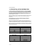
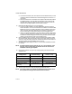
CLASS 2000 METER 6.4 Fixed Pulse Value guide for Class 1000 & 2000, kWh & or kW Demand Meter Color Code Key of Sensor Arrow Must Match the Amperage of Meter: Purple White 25 Amp 50 Amp Watt Hours per Pulse 0.48828 0.97656 Brown 100 Amp 1.95312 Red 200 Amp 3.90625 Yellow 400 Amp 7.81250 Black 800 Amp 15.6250 Blue 1600 Amp 31.2500 Two Blue 3200 Amp 62.500 Pulse output signal is a 50/50 duty cycle.
CLASS 2000 METER MENU DOWN UP SELECT M33183 Fig. 20. Hardware Functions.
CLASS 2000 METER 7.0 KWH/DEMAND METER FEATURES & FUNCTIONS* (*Applies to meters equipped with the Demand Option [-D-], for example: E20-208400-J-D-KIT.) 7.1 KWh/Demand Meter Display Functions The Class 2000 kWh/Demand meter has a single display window that cycles through the energy data screens. The meter will cycle through five (5) separate screens. The screens are described below. KWh display shows the amount of energy consumed in kilowatt hours (kWh).
CLASS 2000 METER 7.2 How to Read the kWh/Demand Meter Fig. 22. KWh Reading. The Class 2000 kWh meter displays readings in whole numbers, there are no decimals. To find the dollar cost for the power used by the load(s) being monitored, you must first find out what the cost per kWh is in your area (this cost can be found on your utility electric bill, or call your local utility and ask for their cost per kilowatt hour.) Simply multiply the cost per kWh by the kWh reading from the E-Mon D-Mon meter.
CLASS 2000 METER 7.3 Demand Display Set-Up HOME DOWN UP ENTER M33207 The demand meter display is set-up using the four buttons located on the meter display board which is mounted on the door inside the meter enclosure. STEP 1: Press the HOME button to enter the menu screen. STEP 2: Press the DOWN button to enter the setup screen. STEP 3: Press the ENTER button to enter the DATE screen. STEP 4: Press the Enter button to cycle between the day, month, and year.
CLASS 2000 METER STEP 6: Press the DOWN button to access the TIME screen. STEP 7: Press ENTER to cycle between the hour, minutes, and day of week selection Use the UP and DOWN buttons to change the selection. STEP 8:When the changes are completed press the ENTER button to save the changes. STEP 9: Press ENTER to enter the DEMAND INTERVAL screen. STEP 10: Press ENTER again to access the interval selection screen. Use the UP and DOWN buttons to select the appropriate interval time. (default is 15 min.
CLASS 2000 METER STEP 12: Press the HOME button to return to the setup screen. STEP 13: Press the UP arrow to display the MENU screen. STEP 14: Press the ENTER button to enter the normal display screen. 7.4 Demand RESET STEP 1: Press the HOME button to access the Series 2000 MENU screen.
CLASS 2000 METER STEP 2: Use the UP and DOWN buttons to access the CHECKOUT screen. STEP 3: Press the ENTER button to access the kw RESET screen. STEP 4: Press ENTER to access the RESET select screen. Use the UP and DOWN buttons to select “yes” or “no”. Press ENTER to save the selection. “Change stored” will be displayed after pressing ENTER. STEP 5: Press the HOME button to return to the menu screens. Use UP and Down to select the STATUS screen. STEP 6: Press ENTER to return to the normal display.
CLASS 2000 METER 7.5 Test Mode MENU UP DOWN SELECT M33183 Fig. 24. Press and release both the Up and Down arrow buttons simultaneously to activate the Test Mode. Test Mode activates a 3-screen auto scrolling display. Each of the 3-screens will display for five-seconds then returning the LCD to normal scrolling mode kWh and kW LOAD displays. 1. Test Mode screen one: LCD Segment Test (32 zeros) 0000000000000000 0000000000000000 2.
CLASS 2000 METER 7.5.1 Test Mode Menu, Setup, And Checkout Features A delay of twenty-seconds between any button choice and the screen will automatically return to normal kWh and kW LOAD mode. MENU DOWN UP SELECT M33183 Press and release Menu Button displays MENU. CL2000 MENU Press and release Down Button displays SETUP. CL2000 SETUP Press & release the Down Button again displays CHECKOUT. CL2000 CHECKOUT Press & release the left Select Button displays CHECKOUT VOLTS A. CHECKOUT VOLTS A 121.
CLASS 2000 METER Press & release Down Button again displays CHECKOUT AMPS A. CHECKOUT AMPS A 0.2V Press & release Down Button again displays CHECKOUT AMPS B. CHECKOUT AMPS B 0.2V Press & release Down Button again displays CHECKOUT AMPS C. CHECKOUT AMPS C 0.2V This concludes the Class 2000 kWh meter advanced display features and instructions. 8.0 PREVENTATIVE/SCHEDULED MAINTENANCE The Class 2000 kWh/Demand meter is shipped in a calibrated, tested and fully functional condition.
CLASS 2000 METER 9.0 LITHIUM BATTERY REPLACEMENT INSTRUCTIONS (*Applies to meters equipped with the Demand Option [-D-], for example: E20-208400-J-D-KIT.) The Class 2000 kWh/Demand meter has a Lithium Battery Cell, which is used to retain the contents of SRAM and the RTC during power outages. The battery has a life expectancy of greater than 5 years. BATTERY M33208 Fig. 25. Battery Location.
CLASS 2000 METER WARNING WARNING: Only replace battery with Panasonic part number CR2032 only. Use of another battery may present a risk or explosion. See owners manual for safety instructions. Internal circuit card components are extremely sensitive to electrostatic discharge. Be careful not to touch internal circuitry prior to discharging any static buildup on your person. To discharge yourself, touch a grounded metal object such as conduit or a metal enclosure exterior.
CLASS 2000 METER 10.0 TROUBLESHOOTING GUIDE The Class 2000 kWh/Demand meter is calibrated and tested at the factory before being packaged and shipped. If installed properly and in accordance with these installation instructions, your Class 2000 meter should provide years of trouble free service. If the meter should not function, the following guide will assist in troubleshooting the installation. Problem Procedure to follow 1. Display window is blank. Check wiring to voltage terminals.
CLASS 2000 METER 10.1 Line Voltage Diagnostics E-Mon meters detect the direction of rotation of three-phase power. The proper phase sequence must be A-B-C. The AC power input must be in proper phase sequence A, B, C. If incorrect, the display will read “Check Install.” See Fig. 28. Fig. 28. Check Install Error. How to Verify & Resolve a Phase Sequence Error CAUTION Dangerous voltage is present inside the meter! The following steps are for Qualified Electrical Service Personnel only. 1. 2. 3. 4.
CLASS 2000 METER A light load or circuit with no load will cause the “Check Install” to be displayed, for example a transformer with no load. The meter must have at least 1% load for each current sensor. For example model number E20-208200-(J or R)-KIT is 200 amp rated; each of the current sensors must have at least two amps flowing though them to verify installation. If the “Check Install” message goes off with 1% or more load, then there is no issue with installation.
CLASS 2000 METER How do I know line from load? Generally speaking, “line” is the power coming in or “upstream” to a circuit breaker/ fuse/disconnect/etc. “Load is the power going out (“downstream”) of the device that interrupts power. If you put a voltage meter on each side (presuming that your switch/ breaker/fuse/whatever is working correctly), then when you switch it on and off, the load side is what goes on and off and the line side is what stays hot no matter what (see Fig. 29). Fig. 29.
CLASS 2000 METER 11.0 HIGH VOLTAGE METERING kWh Meter Installation Instructions for Use with E-MON Meters in High Voltage Applications The E-MON model number containing “12025HV” kWh meter is designed to be used for monitoring high voltage (2400, 4160, 13200, etc) circuits, either “stand alone” or in an AMR application. This meter is intended to be used with the appropriate high voltage Potential Transformers (PTs) and Current Transformers CTs) supplied by others.
CLASS 2000 METER M34227 Fig. 30. High Voltage CTs. M34228 Fig. 31. Wiring Diagram For 3-wire High Voltage Circuits.
CLASS 2000 METER This special high voltage meter installation shows the correct wiring procedure for 3wire high voltage circuits. In this application, the 2 element meter connection is used on the secondary circuits of the user supplied high voltage PTs and CTs. The E-MON meter used in this application is the model containing “12025 HV”. Installation of these meters requires the use of two (2) current sensors mounted on the secondaries of the high voltage Current Transformers.
CLASS 2000 METER 12.0 FREQUENTLY ASKED QUESTIONS Q. When providing line voltage to the meter, can I tap off of the same breaker I am monitoring? A. Yes, the voltage can be pulled from the same breaker being monitored. Q. Can the meter’s line voltage wires be run in the same conduit as the sensor leads? A. Yes, there will be no effect on the meter if the sensor leads and line voltage wires are run in the same conduit. Q. Can the meter communication wires and line voltage wires be run in the same conduit? A.
CLASS 2000 METER Q. The load I need to monitor has parallel feeds. How do I install the current sensors for this application? A. There are two ways you can monitor parallel feeds. One method is to clamp the sensors around all feed wires for each phase (no additional reading multiplier required).
CLASS 2000 METER 13.
CLASS 2000 METER Input Voltage Configuration 3-wire (Delta) Or 4-wire (Wye) Mains Voltage Input Up To 480 VAC RMS Available Input Power 6 VA Maximum Rating Current Sensor Rating Up To 3200 Amps RMS AC Available Power Factor 0.5 Leading Or Lagging Line Frequency 50-60 Hz Metering Accuracy Meets ANSI C12.
CLASS 2000 METER Modem Interface IDR Interface Port Cable: UL-listed Telephone Cord, 6-cond. 300 VAC, Stranded Cond. 22-26 AWG. Cable Connector: RJ-45 male IDC Input/Output Voltage: +5 VDC/18 VAC Ckt Input Isolation 5.3K VAC for 1 Minute Baud Rate: 9600 Cable: UL-listed/rated Telephone Cord. 4-cond. Input/output Voltage: Ground-isolated +/-5.4VDC Cable Connector: RF-45 Male IDC Or Screw Terminal Termination Circuit Input Isolation: 5.3kVAC Circuit output Isolation: 21.
CLASS 2000 METER 14.0 LIMITED METER WARRANTY Subject to the exclusions listed below, E-Mon will either repair or replace (at its option) any product that it manufactures and which contains a defect in material or workmanship. The following exclusions apply: 1. 2. 3. 4. 5. 6. 7. 8. This Limited Warranty is only effective for a period of (5) five years following the date of manufacture when installed in accordance with manufacturer’s instructions by qualified personnel.
CLASS 2000 METER 62-0389-05 50
CLASS 2000 METER 51 62-0389-05
CLASS 2000 METER E-Mon 850 Town Center Drive Langhorne, PA 19047 www.emon.com info@emon.com ® U.S. Registered Trademark © 2014 E-Mon 62-0389—05 M.S. Rev.