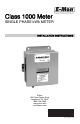
Class 1000 Meter SINGLE PHASE kWh METER INSTALLATION INSTRUCTIONS E-Mon 850 Town Center Drive Langhorne, PA 19047 (800) 334-3666 www.emon.com info@emon.
CLASS 1000 METER Dear Valued Customer, We are pleased that you chose to buy one of our products, and want you to be just as pleased with owning it. Before installing your new E-Mon product, please read the information on the following pages carefully. We believe that you will find the E-Mon D-Mon meters easy to install and to use for monitoring and evaluating your electrical usage.
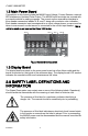
CLASS 1000 METER TABLE OF CONTENTS Section 1.0 Section 1.1 Pre-Installation Information Internal Electronic Assemblies 4 5 Section 1.2 Main Power Board 6 Section 1.3 Display Board 6 Section 2.0 Safety Label Definitions and Information 6 Section 3.0 Precautionary and Safety Information 7 Section 4.0 Meter Installation 8 Section 4.1 Mounting the Meter 8 Section 4.2 Main Power Board Connections 8 Section 4.3 Current Sensor Installation & Wiring 11 Section 4.
CLASS 1000 METER 1.0 Pre-Installation Information The E-Mon D-Mon® Class 1000 kWh meter is a 2-element meter used to monitor electric power usage of individual loads after the utility meter. Installation must only be performed by qualified personnel and in accordance with these instructions and all applicable local and national electrical codes. E-Mon or its representatives assume no responsibility for damages or injury resulting from the improper installation of this meter.
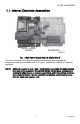
CLASS 1000 METER 1.1. Internal Electronic Assemblies DISPLAY AND KEYBOARD MAIN POWER BOARD M33177 Fig. 1. Main Power Supply Board & Display Board The unit is comprised of a Main Power Board and Display and Keyboard. All component cards are mounted inside a UL Type 1 (standard) or NEMA 4X (optional) enclosure. NOTE: Units are supplied in a UL Type 1 metal enclosure suitable for indoor applications only.
CLASS 1000 METER 1.2 Main Power Board Connections to this board include the MAINS Input Voltage, Current Sensors, external IDR interface and Isolated Pulse Output. The MAINS input terminals are covered with a protective shield for safety purposes. The current sensor assemblies interface to three header connectors labeled A, B, and C along with conductor color indication.
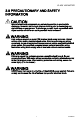
CLASS 1000 METER 3.0 PRECAUTIONARY AND SAFETY INFORMATION CAUTION Internal circuit card components are extremely sensitive to electrostatic discharge. Be careful not to touch internal circuitry prior to discharging any static buildup on your person. To discharge yourself, touch a grounded metal object such as conduit or an earth-grounded metal enclosure. WARNING High voltages present on main PCB terminal block screw terminals. Risk of serious injury and/or electrical shock exists.
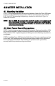
CLASS 1000 METER 4.0 METER INSTALLATION 4.1 Mounting the Meter STEP 1: Using the appropriate sized mounting hardware, fasten the Class 1000 meter enclosure to the selected mounting surface. The four mounting holes are centered 6.75” H x 4” W. The mounting hole spacing is identical for either the UL Type 1 or NEMA 4X enclosure. NOTE: Only the NEMA 4X enclosed unit is suitable for outdoor environmental conditions.
CLASS 1000 METER WARNING Failure to attach the protective earth ground wire securely to the enclosure creates a potential shock hazard. Do not operate the Class 1000 meter without a protective earth ground connection securely installed STEP 3: Wire Entry: Two openings exist on the unit enclosure, one for 1/2” conduit and one for 3/4” conduit. The 3/4” conduit opening located on the bottom of the enclosure is used to bring in MAINS Power (voltage lines to power meter) and current sensor wiring.
CLASS 1000 METER After all conductors are connected to their respective terminal block positions and tightened down, verify that each terminal block screw is securely fastened by gently tugging on each conductor. Verify that no conductor wires are frayed or are shorting to adjacent terminal block positions. STEP 5: External Switch Mechanism/In-Line Fuse Installation.
CLASS 1000 METER 4.3 Current Sensor Installation & Wiring Once the AC voltages have been confirmed to be within acceptable limits, you are ready to install the current sensors. The MAIN power board contains three header connectors located at the bottom right of the board. The connectors are labeled A, B, and C along with conductor color indication. This format must be followed in order for the meter to function correctly.
CLASS 1000 METER 4.4 Installing the Split-Core Current Sensor Assembly STEP 1: Each phase being monitored will require one two-piece current sensor assembly. Therefore, a three-phase meter will require three (3) assemblies. Open the two-piece current sensor assembly by releasing the nylon clamp using a flat head screwdriver. Fig. 3. Split-Core Current Sensor STEP 2: Reassemble the current sensor assembly around the conductor(s) to be monitored.
CLASS 1000 METER 4.5 Installing the Solid-Core Current Sensor Assembly The optional solid-core current sensors can be installed in the same applications as the standard split-core units, however, the conductors that they are monitoring must first be disconnected. NOTE: Under no circumstances is this operation to take place without shutting off the power to the conductor(s) being monitored. With the power off, disconnect the conductor from its breaker or terminal.
CLASS 1000 METER 4.6 Current Sensor Wiring Once all the current sensors are installed on their appropriate phase conductors, you can begin terminating the current sensors on to the Class 1000 main power board. The current sensor leads can be extended up to 2,000 feet (using #14-22 AWG wire) for remote monitoring applications. Consult your local electrical codes for proper wire sizing (#22 AWG twisted pair wire with a black and white conductor, rated for 600 VAC recommended.
CLASS 1000 METER SINGLE-PHASE, 3-WIRE CONNECTION 120/240-VOLT SINGLE-PHASE LINE VOLTAGE ∅A ∅B ∅C 1 N PE CURRENT SENSORS ∅A ∅B WB WB 1 ∅A ∅B LOAD SOURCE N NOTES: LINE VOLTAGE CONNECTION: #14 AWG SENSOR CONNECTION: B = BLACK W = WHITE IMPORTANT: LINE VOLTAGE MUST BE PRESENT AT THE A- AND B-PHASE VOLTAGE TERMINALS. SHORTING LINK MUST BE INSTALLED ON C-PHASE CURRENT SENSOR TERMINALS. 1 1/10-AMP INLINE FUSES RECOMMENDED. M33180 Fig. 7.
CLASS 1000 METER 4.8 Line Voltage/Current Sensor Diagnostics M33181 Fig. 8. Main Board Configuration If the meter is not correctly wired, the “ERROR” indicator will be on. Verify that the AC MAINS voltage wires are all connected to the correct positions on the terminal block. Inspect the MAINS input wiring to verify each conductor is terminated at the correct terminal block position. Using an AC voltmeter, measure the AC voltage for each Phase to Neutral terminal and to the Frame ground point.
CLASS 1000 METER Verify that the current sensor white and black conductors are installed in the correct header positions. Verify that the current sensors are installed in the correct direction on the conductor being monitored. Verify that the current sensor plugs are terminated in the correct header on the Main power board. If the error LED still hasn’t been cleared, measure the AC voltage inputs across the plug terminals of each current sensor, individually. Set the AC voltmeter to the 20 Volt scale.
CLASS 1000 METER 5.0 MONITORING MULTIPLE LOADS WITH ONE METER The Class 1000 meter provides extreme flexibility by allowing additional sets of current sensors to be used in parallel so that multiple load locations can be monitored by one meter. This feature allows a totalized display readout from two or more load circuits. You may use parallel sensors to monitor specific breakers from one panel, specific breakers from more than one panel, two or more complete panels, etc.
CLASS 1000 METER CURRENT SENSORS ØA ØB ØC ØAØB ØC N PE W B W B W B LINE VOLTAGE ØA ØB LOAD SOURCE LOAD A N ØA ØB LOAD SOURCE LOAD B N M33204 Fig. 9. Multiple Load Locations Can Be Monitored By One Meter.
CLASS 1000 METER 6.0 KWH METER FEATURES & FUNCTIONS 6.1 KWh Meter Display Functions Fig. 10. Normal Mode (kWh Reading) The Class 1000 kWh meter display requires no multiplier and shows kilowatt hours consumed. See section 6.2 for information on calculating cost based on kWh usage. Fig. 11. KW Load Mode (Current Load in kW) The Class 1000 LOAD display shows the present circuit load in kilowatts. Fig. 12. Start Up Mode When initially powered on, the Class 1000 meter will display the startup screen.
CLASS 1000 METER 6.2 How To Read The kWh Meter Fig. 13. The Class 1000 kWh meter displays readings in whole numbers, there are no decimals. To find the dollar cost for the power used by the load(s) being monitored, you must first find out what the cost per kWh is in your area (this cost can be found on your utility electric bill, or call your local utility and ask for their cost per kilowatt hour.) Simply multiply the cost per kWh by the kWh reading from the E-Mon D-Mon meter.
CLASS 1000 METER 6.3 KWh Meter Hardware Functions IDR Jack 8-pin RJ-45-used to connect kWh meter to the EMon Energy automatic meter reading system. Calibration Jack Connector J11 is for factory calibration only, and is not a user accessible port. Silicon plug is not to be removed. Error LED When lit, indicates that the current sensor is backwards or on the incorrect phase. Meter Pulse LED Blinks to show the meter load. Blink rate increases with load.
CLASS 1000 METER MENU DOWN UP SELECT M33183 Fig. 15.
CLASS 1000 METER 7.0 PREVENTATIVE/SCHEDULED MAINTENANCE The Class 1000 kWh/single phase meter is shipped in calibrated, tested and fully functional condition. - No field adjustments are required. - No preventative or scheduled maintenance is required. - No cleaning or decontamination procedures are required for this instrument.
CLASS 1000 METER 8.0 TROUBLESHOOTING GUIDE The Class 1000 kWh/single phase meter is calibrated and tested at the factory before being packaged and shipped. If installed properly and in accordance with these installation instructions, your Class 1000 meter should provide years of trouble free service. If the meter should not function, the following guide will assist in troubleshooting the installation. Problem Procedure to follow: 1. Display window is blank. a. Check wiring to voltage terminals. b.
CLASS 1000 METER 9.0 FREQUENTLY ASKED QUESTIONS Q. When providing line voltage to the meter, can I tap off of the same breaker I am monitoring? A. Yes, the voltage can be pulled from the same breaker being monitored. Q. Can the meter’s line voltage wires be run in the same conduit as the sensor leads? A. Yes, there will be no effect on the meter if the sensor leads and line voltage wires are run in the same conduit. Q. Can the meter communication wires and line voltage wires be run in the same conduit? A.
CLASS 1000 METER Q. The load I need to monitor has parallel feeds. How do I install the current sensors for this application? A. There are two ways you can monitor parallel feeds. One method is to clamp the sensors around all feed wires for each phase (no additional reading multiplier required).
CLASS 1000 METER 10.
CLASS 1000 METER Altitude 2000 Meters Maximum Voltage Overload +25% Continuously: +100% For 20 Cycles Current Sensor Overload 100% For 1 Minute Without Damaging Meter Pollution Degree Degree 2 In Accordance With IEC 664 Installation (Overvoltage) Category Category 3 Measurement Category Category 3 Enclosure Material Indoor Housing Rating (Standard): UL Type 1 Outdoor Housing Rating (Optional): NEMA 4X Display Readout KWh Accumulated, Instantaneous kW Standard Ranges 3-wire 115/208 Vac; 25,5
CLASS 1000 METER 11.0 METER LIMITED WARRANTY Subject to the exclusions listed below, E-Mon will either repair or replace (at its option) any product that it manufactures and which contains a defect in material or workmanship. The following exclusions apply: 1. 2. 3. 4. 5. 6. This Limited Warranty is only effective for a period of (5) five years following the date of manufacture when installed in accordance with manufacturer’s instructions by qualified personnel.
CLASS 1000 METER 7. 8. This Limited Warranty is limited to the obligation to repair or replace the manufactured product. This is the sole and exclusive remedy for any breach of warranty.
CLASS 1000 METER E-Mon 850 Town Center Drive Langhorne, PA 19047 www.emon.com info@emon.com ® U.S. Registered Trademark © 2011 E-Mon 62-0388-01 JPG Rev.