PowerSmart Socket POWER QUALITY METER Installation Manual BG0549 Rev.
DANGER This symbol indicates the presence of dangerous voltage within and outside the product enclosure that may constitute a risk of electric shock, serious injury or death to persons if proper precautions are not followed. CAUTION This symbol alerts the user to the presence of hazards that may cause minor or moderate injury to persons, damage to property or damage to the device itself, if proper precautions are not followed.
DANGER Failure to observe the following instructions may result in severe injury or death. Read the instructions in this manual before performing installation, and take note of the following precautions: 1. Ensure that all incoming AC power and other power sources are turned OFF before performing any work on the instrument. Failure to do so may result in serious or even fatal injury and/or equipment damage. 2.
Table of Contents Chapter 1 Introduction ................................................................ ............................................................................... ............................................... 1 About This Manual ................................................................ ................................................................................................ ...................................................................... .........................
FIGURES Figure 1: Front view - Nameplate description................................ ................................................................ ................................................................. .................................3 Figure 2: PowerSmart Socket PQM - FORM 9S Dimensions................................ ........................................ ........5 ................................ ........ 5 Figure 3: PowerSmart Socket PQM internal structure ..............................
Chapter 1 Introduction About This Manual This manual is intended to assist the user in the installation of the PowerSmart Power Quality Meter unit. The term ‘PowerSmart Socket PQM’’ is used herein to refer to all models in the series. This chapter gives an overview of this manual and an introduction to the PowerSmart Socket PQM. Chapter 2, Installation, provides instructions for mechanical and electrical installation.
Low Range measurement input nominal rating – "U" Model: 57.7V AC to 120V AC (LN) − High Range measurement input nominal rating – standard Model: 120V AC to 277V AC (L-N) On board 2 Digital optically isolated Fast Inputs and 1 KYZ relay output.
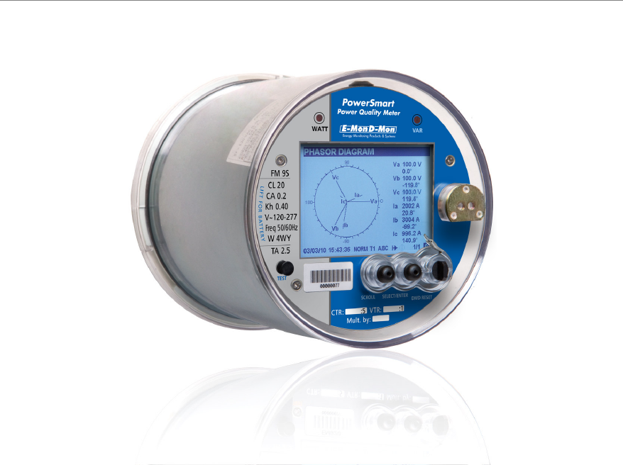
Socket Meter Overview Figure 1: Front view - Nameplate description Chapter 1 Introduction 3
Chapter 2 Installation The PowerSmart Socket PQM Socket meter is designed to mount into a standard meter socket. Follow the Installation summary below, to ensure that the unit is installed securely. The PowerSmart Socket PQM series can be mounted outside or in an enclosed and protected environment, such as in a switchgear cabinet. You may install a switch or circuit breaker nearby and label it clearly as the monitor’s disconnecting mechanism.
Mechanical Installation Refer to the figures provided in this section to properly perform the mechanical installation.
Physical Description Device Structure F i g u re 3: P o w e r S m a rt S o c k e t P Q M i n te r n a l s t ru c t u re Optional Modules location F i g u re 4: P o w e r S m a rt S o c k e t P Q M i n te r n a l s t ru c t u re 6 Chapter 2 Installation
Meter Ex ter nal connections F i g u r e 5: M e te r B a s e – re ar v i e w Chapter 3 Communication 7
Electrical Installation Before installing, ensure that all incoming power sources are shut OFF. Failure to observe this practice can result in serious or even fatal injury and damage to equipment. Voltage Inputs There are 3 AC Y-connected voltage inputs of 100-480 VAC (phase-to-phase) and neutral, via socket meter blades.
Wiring Configuration Wiring Setup FORM factor 4-wire 4-wire 4-wire 4-wire 3-wire 4Ln3 4Ln3 4LL3 4LL3 3OP3 9S 9S 9S 9S 5S/35S 3-wire 2½-element Open Delta connection using 2 PTs, 3 CTs 3OP3 5S/35S 3-wire 2-element Open Delta using 2 CTs 4-wire WYE 2½-element connection using 3 CTs 3OP2 3Ln3 6S/36S 4-wire WYE 2½-element connection using 2 PTs, 3 CTs 3Ln3 6S/36S 4-wire 2½-element delta connection using 2 PTs, 3 CTs 3LL3 WYE 3-element using 3 CTs WYE 3-element connection using 3 PTs, 3 CTs 3-ele
F i g u re 9 : F o u r W i r e W Y E Co n n e c ti o n U s in g 3 P T s an d 3( 4) C Ts - W i ri n g Se tu p : 4 L n 3 F i g u r e 1 0 : F o u r W i r e D E L TA Co n n e c ti o n U s i n g n o P Ts a n d 3 ( 4) C T s W i ri n g Se tu p : 4 L L 3 10 Chapter 2 Installation
F i g u re 1 1: F o u r W ir e D E L TA C o n n e c ti o n U s i n g 3 P Ts a n d 3 C Ts - W i ri n g Se tu p : 4 L L 3 F i g u re 1 2: T h re e W i r e D E L T A C o n n e c t io n U s i ng n o P T s a n d 2 C T s - W i ri n g S e t u p : 3O P 3 Chapter 3 Communication 11
F i g u r e 1 3 : T h re e W i re D E L T A Co n n e c t i o n U s i ng 2 P Ts a n d 2 CTs - W i ri n g S e t u p : 3O P 3 12 Chapter 2 Installation
Input / Output ports options Before I/O Module installation ensure that all incoming power sources are shut OFF. Failure to observe this practice can result in serious or even fatal injury and damage to equipment. On b o a rd I / O p o rt s L O G I C/ D I SP L A Y The PowerSmart Socket PQM LOGIC/DISPLAY board is equipped with two fast Dry contact detector – Digital Inputs 2DI unit, providing wet contact voltage of 24VDC, RS-485 communication port COM3 and USB device port.
Op ti on al I / O m od ul es 8DI The 8DI module consists of eight status inputs detection.
R e l ay O u tp u ts ( 6 R O – o p t i o n a l m o d u l e ) The 6RO module consists of: four FORM C (SSR) and two FORM A (EMR) relay outputs.
F i g u re 1 9 : 4 A O Co n n e c ti o n It is recommended to connect unused Analog output channels to Common terminal.
T r an si en t s R ec ord er M od u l e (T R M – op t ion a l mod u l e ) The PowerSmart Socket PQM Transients Recorder module provides four input voltages transient measurement related to ground: V1 (L1-G), V2 (L2-G), V3 (L3-G) and VN (N-G) To install the TRM module follow instructions: 1) Remove the plastic cover 2) Remove the body shield 3) Plug-in the module in the TRM slot and attach it to bracket using the two screws 4) Mount back the body shield 5) Mount back the plastic cover The TRM module is facto
Communications options The PowerSmart Socket PQM has several communication alternatives depending on your ordering preferences. All communications ports, of different type, can be used simultaneously. The basic PowerSmart Socket PQM is equipped with one standard optical communication port (COM1), an optically isolated RS-485 communication port (COM3) and an USB Device Type A. Other COM ports are available as optional module.
U S B Co m m u n i c a ti o n p o r t ( U SB – o n b o a rd ) The PowerSmart Socket PQM provides a standard full speed USB DEVICE port.
3) Plug-in the module in the COM slot and attach it to bracket using the two screws 4) Connect the GSM/GPRS antenna cable expander and pass it through the device base window cables 5) Mount back the body shield 6) Mount back the plastic cover The GSM/GPRS module is factory or Meter Shop plugged-in at the COM slot 1) Apply power to the meter 2) After one minute the "LNK" GREEN LED is flashing until it lights "ON" continuously 3) The "RSSI" ORANGE LED will light "ON" or blinks, the flashing rate is proportion
Figure 26: MODEM module R S - 48 5/ 2 3 2 Co m m u n i c at i o n p o rt ( CO M 4 – E TH o r M O D E M optional modules) The RS-485/232 Communication port – COM4 is provided by ETH optional module.
R S - 23 2 m o d e In the RS-232 mode, the 485/232 wire must be tied to GND wire as shown in figure 28 F i g u re 2 8: Se ri al C o m m u n ic at i o n C o n n e c ti o n – R S - 23 2 CO M 4 IRIG-B 1-ms satellite-synchronized clock from a GPS satellite clock that has an IRIG-B time code output connected to the IRIG-B input port. Connect the GPS receiver IRIG-B output to the IRIG-B/GND wires respectively.
F i g u re 3 0: M O D E M c o n n e c t i o n The MODEM module provides additionally to COM4 indication GREEN LEDS, MODEM indication leds : "LNK" GREEN LED/ "ACT" ORANGE LED, when "LNK" is "ON" continuously and "ACT" is blinking, it shows that the MODEM is active Auxiliary Power Supply A C/ D C A u xi li ar y P o we r Su p p ly The PowerSmart Socket PQM- 120V model only, can be equipped with additional power supply to redundant the built-in power supply (Auxiliary Power Supply – APS).
The AC/DC APS module provide one indication GREEN LED: "PWR" GREEN LED: is "OFF" if AC/DC APS cable is disconnected or no power source is applied to it is "ON" if power is applied to AC/DC APS cable 24 Chapter 2 Installation
Chapter 3 Communications 1.
Chapter 4 Replacing the Battery When the battery level drops below the minimum allowed threshold, the LCD graphic display, on the front of the device, shows: , indicating that the battery should be replaced.
Appendix: Technical Specifications Inputs Ratings AC Voltage inputs Va, Vb, Vc and Vref - 50/60Hz Reference voltage Un 120V up to 277V L-N (direct) standard Voltage rating: 120 up to 277 Volts (L-N), 207 to 480 Volts (L-L) Reference voltage Un 57.73V up to 120V L-N (via PT) optional Voltage range Crest factor >2 [VL-N x 1.2 x 2] High input impedance = 10MΩ Ω 0 -332 V r.m.s, peak up 665V (for PQ) Maximum Line to Line voltage 1152 V r.m.
Power Supply Power supply Supplied from Monitored Voltage inputs 480V model standard (direct) Three Phase PS, Rated Inputs (L-N) 50/60 Hz 120 – 277V AC ± 20% Operating voltage range 96 – 550V AC Insulation Dielectric withstand 2500V AC @ 1mn Operating Temperature range -40ºC to + 75ºC Output voltage +12V DC ± 5% Burden per phase 6VA 120 V model optional Three Phase PS, Rated Inputs 50/60 Hz (via PT) Operating voltage range 57.
Terminals for wires size Blades (Socket meter standard – C12.10) Relay Output Digital output – combined SSR + EMR 4 x FORM C + 2 x FORM A 6RO Optional module1 SSR – 4 relays (FORM C) 0.
Communication ports COM1 Built-in Infra Red communication port DISPLAY unit IR port Basic RS232 communication, TTL level, max baud rate 19.2 kb/s Protocols MODBUS RTU/ASCII and DNP3.0 Optically isolated 2500V AC @ 1mn Optical port per ANSI C12.18 Type 2 COM2 Plug-in modules isolated communication port GSM/GPRS MODEM Optional module1 RS232 communication, TTL level, max baud rate 115.
IRIG-B ETH-TX MODEM Optional module1 USB connector Cable terminated with USB type A Input Isolation 2500V AC @ 1mn Time code signal Demodulated (pulse-width coded) Signal Level Unbalanced 5V Terminals for wires size 2 x 2.
Immunity Surge – IEEE C62.41.2-2002 100kHz ring wave 1.2/50 µs – 8/20 µs 6kV / 0.5kA 6kV / 3kA Magnetic field – ANSI C12.1 FTB – IEC 61000-4-4, level 4 4kV – measuring inputs 2kV – I/O and com. SWC – IEEE C37.90.1 2.5kV – measuring inputs, I/O an com. Electromagnetic RF Fields – ANSI C12.1 20V/m @ 200kHz – 10GHz ESD - IEC61000-4-2 15KV – air Emission Radiated / Conducted - FCC/CFR 47 p.15 Class B Safety ANSI C12.1 Environment Insulation, ANSI C12.1 2.5 KV r.m.s.
Measurement Specifications Parameter Full Scale @ Input Range Accuracy % Reading Range % FS Conditions Voltage V1-V3 (L-n) 277 x PT ratio @ 277V ±0.05 ±0.1 1% up to 120% 0 up to 999,000 V Voltage V1-V3 (L-n) 120 x PT ratio @ 120V ±0.05 ±0.1 1% up to 140% 0 up to 999,000 V Voltage V1-V3 (L-n) 69 x PT ratio ±0.05 ±0.1 1% up to 140% 0 up to 999,000 V Line current I1- I3 CT primary current ±0.06 ±0.06 1% up to 200%In 0 up to 20,000 A Line current I1- I3 CT primary current ±0.
34 Appendix: Technical Specifications