
Owner manual


Chapter 5 Configuring the PowerSmart Socket PQM
Configuring Recorders
PowerSmart Socket Power Quality Meter 115
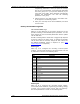
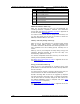
Data Log #2
No. Parameter
1 V1/V12 demand
2 V2/V23 demand
3 V3/V31 demand
4 I1 demand
5 I2 demand
6 I3 demand
7 kW import (delivered) sliding demand
8 kvar import (delivered) sliding demand
9 KVA total sliding demand
10 kWh import (delivered)
11 kWh export (received)
12 kvarh import (delivered)
13 kvarh export (received)
14 kVAh total
15 In
16 Frequency
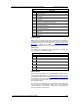
Data Log #13
Data Log #13 is linked to the Fault recorder and is configured
for fast 1/2-cycle RMS profiling of fault events. You can freely
manipulate this file, as you want. See Configuring the Fault
Recorder in Chapter 5 on how to enable or disable RMS
profiling and how to define the maximum duration of the fault
RMS profiles.
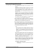
The factory pre-configured list of parameters for Data log
#13 is shown in the following table.
Data Log #13
No. Parameter
1 1/2-cycle voltage V1/V12
2 1/2-cycle voltage V2/V23
3 1/2-cycle voltage V3/V31
4 1/2-cycle (neutral/zero-sequence) voltage V4
5 1/2-cycle current I1
6 1/2-cycle current I2
7 1/2-cycle current I3
8 1/2-cycle current I4
9 1/2-cycle zero-sequence voltage
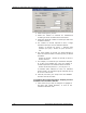
Data Log #14
Data Log #14 is linked to the Power Quality recorder and is
configured for RMS profiling of power quality events. You can
freely manipulate this file. See EN50160 PQ Recorder Setup
in Chapter 5 on how to enable or disable RMS profiling and
how to define the maximum duration and time envelopes for
the PQ RMS profiles.
The factory pre-configured list of parameters for Data log
#14 is shown in the following table. The time integration
interval for these parameters is dynamically changed as the
event continues for more time.