
Instruction Manual


PowerSmart+ Power Quality Meter 145
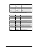
Display Code Designation Description
Time and Date Parameters
Day of Week DAY OF WEEK Day of week
Year YEAR Year
Monh MONTH Month
Day of Month DAY OF MONTH Day of month
Hours HOURS Hours
Minutes MINUTES Minutes
Seconds SECONDS Seconds
Minute Interval MINUTE INTERVAL Minute interval: 1-5, 10, 15, 20, 30, 60 min
1
In 4LN3, 3LN3 and 3BLN3 wiring modes, the voltages will be line-to-neutral; for
any other wiring mode, they will be line-to-line voltages.
Table 24: Setpoint Actions
Display Code Designation Description
None NONE None (no action)
Relay 1 ON OPERATE RELAY #1 Operate relay RO1
Relay 2 ON OPERATE RELAY #2 Operate relay RO2
Relay 3 ON OPERATE RELAY #3 Operate relay RO3
Relay 4 ON OPERATE RELAY #4 Operate relay RO4
Relay 1 OFF RELEASE RELAY #1 Release latched relay RO1
Relay 2 OFF RELEASE RELAY #2 Release latched relay RO2
Relay 3 OFF RELEASE RELAY #3 Release latched relay RO3
Relay 4 OFF RELEASE RELAY #4 Release latched relay RO4
Increment counter 1 INC CNT #1 Increment counter #1
Increment counter 2 INC CNT #2 Increment counter #2
Increment counter 3 INC CNT #3 Increment counter #3
Increment counter 4 INC CNT #4 Increment counter #4
Time counter 1 TIME CNT #1 Count operation time using counter #1
Time counter 2 TIME CNT #2 Count operation time using counter #2
Time counter 3 TIME CNT #3 Count operation time using counter #3
Time counter 4 TIME CNT #4 Count operation time using counter #4
Notification NOTIFICATION Send a notification message
Data Log 1 DATA LOG #1 Record data to Data Log #1