500 - E4500 Combustion Analyzer OPERATING & MAINTENANCE MANUAL Respect your environment: think before printing the full manual on paper
TABLE OF CONTENTS 1.0 IMPORTANT INFORMATION 1.1 Introduction 1.2 Safety warnings 07 07 07 2.0 SAFETY 2.1 Intended use of the product 2.2 Improper use of the product 08 08 08 3.0 WORKING PRINCIPLE 3.1 Working principle 3.2 Measuring Sensors 09 09 09 4.0 DESCRIPTION OF THE PRODUCT 4.1 General Description of the Combustion Analyzer 4.2 General Characteristics of the Combustion Analyzer 4.3 Description of the Components of the Combustion Analyzer 4.3.1 Keypad 4.3.2 Display 4.3.3 Printer 4.3.
TABLE OF CONTENTS 8.0 POWER ON - OFF 8.1 Starting the device 23 23 9.0 CONFIGURATION 9.1 Configuration Menu 9.2 Analysis Menu 9.2.1 Configuration=>Analysis=>Fuel 9.2.2 Configuration=>Analysis=>Condensation 9.2.3 Configuration=>Analysis=>O2 reference 9.2.4 Configuration=>Analysis=>NOx/NO ratio 9.2.5 Configuration=>Analysis=>Measuring Units 9.2.6 Configuration=>Analysis=>Autozero 9.2.7 Configuration=>Analysis=>Measures list 9.3 Instrument Menu 9.3.1 Configuration=>Instrument=>Bluetooth 9.3.
TABLE OF CONTENTS 11.2 11.3 11.4 11.5 11.6 Print=>Report Print=>Configuration Print=>Test Print=>Header Print=>Printer 11.6.1 Print=>Printer=>Pairing 11.7 Print=>Measures list 75 76 77 78 80 81 83 12.0 MEASUREMENTS 12.1 12.2 12.3 12.4 12.5 12.6 12.7 Measurements Menu Measurements=>Draft Measurements=>Smoke Measurements=>Ambient CO Measurements=>Temperature Measurements=>Pressure Measurements=>Tightness test 12.7.1 Connection of the tool tightness test kit 12.
TABLE OF CONTENTS 15.4 15.5 15.6 15.8 15.9 Maintaining the water trap / filter unit Replacing the particulate filter Replacing the gas sensors Replacing the battery pack Replacing the printer paper roll 125 125 125 129 130 16.0 TROUBLESHOOTING 131 131 16.1 Troubleshooting guide 17.0 SPARE PARTS AND TECHNICAL ASSISTANCE 17.1 Spare parts 17.2 Accessories 17.
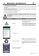
1.0 IMPORTANT INFORMATION 1.1 Information about this manual This manual describes the operation and the characteristics and the maintenance of the Combustion Analyzer model E4500. Read this operation and maintenance manual before using the device. The operator must be familiar with the manual and follow the instructions carefully. This use and maintenance manual is subject to change due to technical improvements - the manufacturer assumes no responsibility for any mistakes or misprints. 1.
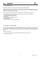
2.0 SAFETY 2.1 Intended purpose This chapter describes the areas of application for which the E4500 is intended. Using the E4500 in other application areas is on the risk of the operator and the manufacturer assumes no responsibility and liability for loss, damage or costs which could be a result. It is mandatory to read and pay attention to the operating/maintenance manual.
3.0 WORKING PRINCIPLE 3.1 Working principle The gas sample is taken in through the gas probe, by a diaphragm suction pump inside the instrument. The measuring probe has a sliding cone that allows the probe to be inserted in any stack with the gas probe tip roughly centered in the flue. The gas sample is cooled, dried and cleaned of humidity and impurities/particulates by a condensate trap and filter positioned along the rubber hose that connects the probe to the analyzer.
4.0 DESCRIPTION OF THE PRODUCT 4.1 General Description of the Combustion Analyzer The design of the handheld combustion analyzer "E4500" is clean and ergonomic with an extremely clear and user-friendly keypad. "E4500" immediately suggests just how even the most sophisticated engineering can give life to an incredibly comfortable and easy to use work instrument.
The use of the analyzer is simplified by the symbol keys with direct access to the most important functions. Navigation through the various menu screens is easy and intuitive.
4.
4.3.1 Keypad Adhesive polyester keypad with keys for main control functions: KEYS FUNCTION KEYS FUNCTION Activates the context keys shown on the display Turns the device On / Off Access to the Memory menu Exits the current screen Access to the Printing menu Select and/or Modify Access to the Configuration menu Confirm/Save settings D i sp l a y s t h e combustion analysis Access to the Measurements menu 4.3.2 Display Date, time and battery status.
4.3.3 Printer Thermal polyester or thermal paper. Thermal polyester cannot be altered and it is resistant to light, temperature, humidity and water. The print menu is accessed by pressing the relative key and, besides enabling read-out printing, the menu also allows you to modify print settings and to feed the paper manually for paper roll replacement. 4.3.4 B-Type USB connector Connector to connect the device to a personal computer or to the battery charger.
5.
6.0 TECHNICAL SPECIFICATIONS 6.1 Technical Specifications Autozero: Dilution (where provided): Gas measurement sensors: Self-diagnosis: Temperature measurement: Measurement of ambient temp.
6.2 Measurement and Accuracy Ranges MEASUREMENT SENSOR RANGE RESOLUTION O2 Electrochemical sensor 0 .. 25.0% vol 0.1% vol CO with H2 compensation Electrochemical sensor 0 .. 8000 ppm 1 ppm ±10 ppm ±5% measured value ±10% measured value diluted Electrochemical sensor 10.00% vol 0.01% vol ±20% measured value CO Low range with H2 compensation Electrochemical sensor 0 .. 500 ppm 0.
7.0 USING THE FLUE GAS ANALYZER 7.1 Preliminary operations Remove the instrument from its packing and check it for damage. Make sure that the content corresponds to the items ordered. If signs of tampering or damage are noticed, notify the E INSTRUMENTS service center or distributor immediately and keep the original packing. A label on the back of the analyzer bears the serial number.
7.3.2 Use with external power pack The instrument can work with the batteries fully discharged by connecting the external power pack provided. THE POWER SUPPLY/BATTERY CHARGER IS A SWITCHING TYPE ONE. THE APPLICABLE INPUT VOLTAGE RANGES BETWEEN 90Vac AND 264Vac. INPUT FREQUENCY: 50-60Hz. THE LOW VOLTAGE OUTPUT IS 5 VOLT WITH AN OUTPUT CURRENT GREATER THAN 1.5A. LOW VOLTAGE POWER CONNECTOR: A-TYPE USB CONNECTOR + CONNECTION CABLE WITH BTYPE PLUG.
7.
7.4.1 Gas sampling probe The gas sampling probe is made up of an INOX steel tube with a plastic hand grip and an internal K-type thermocouple (Ni-NiCr) for measuring the gas temperature up to 1470°F (800°C). Flue gas temperature is measured by means of a thermocouple inserted in the tip of the probe. The thermocouple is connected to the instrument via a compensated cable housed in a special seating in the rubber hose of the sample probe.
7.4.5 Combustion air temperature probe (for Condensing Boilers/Furnaces) The probe to measure the temperature of the combustion air (necessary for an exact calculation of the efficiency of the appliance) features a stainless steel tube with an adapter for wells of the diameter of 7.5 / 17 mm and Ktype internal thermocouple (Ni-NiCr) to measure the temperature between -4°F and 212°F (-20°C and +100°C.) The probe comes complete with an 80” (2 m) cable with a connector for connection with the analyzer. 7.4.
8.0 8.1 POWER ON - OFF Starting the device 07/08/14 10:00 07/08/14 10:00 Combustion analysis Combustion analysis O2 % CO2 % Ex. Air T flue T air ∆T °C °C Press and hold for a few seconds °C Loss tot E4500-N % Serial number: 1000 Firmware version: 1.00 Eff. tot % 4.2 % O2 4.2 9.3 CO2 9.3 % 1.25 Ex. Air 1.25 190.1 T flue 190.1 15.4 T air 15.4 74.7 ∆T 74.7 8.6 91.4 °C °C °C Loss tot % Eff. tot % 8.6 91.
9.0 CONFIGURATION 9.1 Configuration menu 07/08/14 10:00 KEY FUNCTION Activate the context keys shown on the display. Configuration Analysis Instrument Operator Alarms Information Diagnostic Language Restore Returns to the previous screen. CONTEXT KEY FUNCTION ◄ Selects the available parameters. OK Enters in the selected parameter setting. ► Selects the available parameters.
9.2 Configuration→Analysis 07/08/14 10:00 → KEY FUNCTION Configuration Analysis Activate the context keys shown on the display. Fuel Condensation Returns to the previous screen. O2 reference NO x/NO ratio Measure units Autozero CONTEXT KEY FUNCTION ◄ Selects the available parameters. OK Enters in the selected parameter setting. ► Selects the available parameters.
9.2.1 Configuration→Analysis→Fuel 07/08/14 10:00 07/08/14 10:00 Configuration Fuel → Configuration Fuel Natural gas Pellet 8% Propane Wood 20% L.P.G. Woodchips Butane Coal Diesel oil Fuel oil Propane-Air Biogas KEY FUNCTION Activate the context keys shown on the display. The arrows select each line displayed. Confirms the choice of fuel to be used during the analysis. Returns to the previous screen. CONTEXT KEY FUNCTION Shows the details of the selected fuel (see example below).
9.2.2 Configuration→Analysis→Condensation → 07/08/14 10:00 Configuration Condensation Altitude 0 R.H. air 50 m % Altitude above sea level Relative humidity of air KEY FUNCTION Activate the context keys shown on the display. The arrows select each line displayed (the selected line is red). In edit mode, it scrolls through the suggested values. Enters the modify mode for the selected parameter, then confirms the modification.
9.2.3 Configuration→Analysis→Reference O2 → 07/08/14 10:00 Configuration O2 reference % CO 0.0 NOX % 0.0 SO2 0.0 % Percentage of Oxygen in CO measurement Percentage of Oxygen in NOX measurement Percentage of Oxygen in SO2 measurement KEY FUNCTION Activate the context keys shown on the display. Keys '▲' and '▼' select any line shown on the display (the selected line is evidenced in red). When in modify mode, sets the desired value.
9.2.4 Configuration→Analysis→NOX/NO ratio → 07/08/14 10:00 Configuration NOX/NO ratio NOX//NO 1.05 KEY FUNCTION Activate the context keys shown on the display. When in modify mode, sets the desired value. Enters edit mode of the selected element and then confirms the change. When pressed in modify mode cancels the selection made, otherwise returns to the previous screen. CONTEXT KEY FUNCTION Enters edit mode. Confirms the modification.
9.2.
9.2.6 Configuration→Analysis→Autozero → 07/08/14 10:00 Configuration Autozero Autozero 60 Purging 0 s s Duration of autozero, expressed in seconds. Duration of the cleaning cycle, expressed in seconds. O KEY FUNCTION Activate the context keys shown on the display. When in modify mode, sets the desired value. Enters edit mode of the selected element and then confirms the change. When pressed in modify mode cancels the selection made, otherwise returns to the previous screen.
9.2.7 Configuration→Analysis→Measures list → 07/08/14 10:00 Configuration Measures list O2 CO2 Ex. Air T flue T air ∆T Loss tot (PCI) Eff. tot (PCI) » KEY FUNCTION Activate the context keys shown on the display. Select each line displayed (the line selected is red). In edit mode, it sets the desired value. When pressed in modify mode cancels the selection made, otherwise returns to the previous screen. CONTEXT KEY FUNCTION Adds a line to the list of available measurements.
Example: → 1. Add a measurement to the list - example 07/08/14 10:00 Configuration Measures list 07/08/14 10:00 07/08/14 10:00 07/08/14 10:00 Configuration Measures list Configuration Measures list Configuration Measures list O2 O2 O2 O2 CO2 CO2 Ex. Air Ex. Air CO2 T flue T flue Ex. Air T air T air T flue T flue ∆T ∆T T air T air Loss tot (PCI) Loss tot (PCI) ∆T ∆T Eff. tot (PCI) Eff. tot (PCI) Loss tot (PCI) Loss tot (PCI) » O2 ▼ » ▲ OK ▲ CO2 OK Ex.
9.3 Configuration→Instrument 07/08/14 10:00 → KEY FUNCTION Activate the context keys shown on the display. Configuration Instrument Bluetooth Time/Date Brightness Pump CO dilutor Micromanometer Returns to the previous screen. CONTEXT KEY PARAMETER FUNCTION ◄ Selects the available parameters. OK Enters in the selected parameter setting. ► Selects the available parameters.
9.3.1 Configuration→Instrument→Bluetooth → 07/08/14 10:00 Bluetooth Status ID off E4500 - 0001 MAC 00026BB5500 Bluetooth enabling / disabling Instrument name MAC address detected On KEY FUNCTION Activate the context keys shown on the display. Also activates the context key shown on the display. Returns to the previous screen. CONTEXT KEY FUNCTION on Turns on Bluetooth communication. Esc Turns off Bluetooth communication.
9.3.2 Configuration→Instrument→Time/Date → 07/08/14 10:00 Configuration Time/Date Time 3:00 PM Time, in the chosen format Date 7/08/14 Date, in the chosen format Mode USA Date format: USA (American) or EU (European) Mode 12 h Time format: 12h or 24h KEY FUNCTION Activate the context keys shown on the display. When in modify mode, sets the desired value. Enters edit mode of the selected element and then confirms the change.
9.3.3 Configuration→Instrument→Brightness → 07/08/14 10:00 Configuration Brightness 100 KEY FUNCTION Activate the context keys shown on the display. Increases or decreases the brightness of the display. Confirms the modification. When pressed in modify mode cancels the selection made, otherwise returns to the previous screen. CONTEXT KEY FUNCTION ◄ Decreases the brightness of the display. OK Confirms the setting. ► Increases the brightness of the display.
9.3.4 Configuration→Instrument→Pump → 07/08/14 10:00 Configuration Pump Pump on Flow 1.2 l/min Displays the flow of the pump, expressed in litres per minute. KEY FUNCTION Activate the context keys shown on the display. When in modify mode, sets the desired value. Enters edit mode of the selected element and then confirms the change. When pressed in modify mode cancels the selection made, otherwise returns to the previous screen.
9.3.5 Configuration→Instrument→CO dilutor → 07/08/14 10:00 Configuration CO dilutor Mode auto Limit 1500 ppm Available settings: auto, on or off Threshold that activates the dilution pump (available only if the "Mode" parameter is set o "auto". KEY FUNCTION Activate the context keys shown on the display. Select each line displayed (the line selected is red). In edit mode, it sets the desired value. Enters edit mode of the selected element and then confirms the change.
9.3.6 Configuration→Instrument→Micromanometer → 07/08/14 10:00 Configuration Micromanometer Inlet P+ Sets the input used for the test: P+ o P- KEY FUNCTION Activate the context keys shown on the display. In edit mode, it sets the desired input. Enters edit mode of the selected element and then confirms the change. When pressed in modify mode cancels the selection made, otherwise returns to the previous screen. CONTEXT KEY FUNCTION Enters edit mode of the selected parameter.
9.4 Configuration→Operator → 07/08/14 10:00 Configuration Operator Operator 1 Operator 2 Operator 3 Operator 4 Operator 5 Operator 6 Operator 7 Operator 8 KEY FUNCTION Activate the context keys shown on the display. In "edit text": Moves the cursor on the box corresponding to the letter or number required to form the word. In "Operator Configuration": Scrolls through the available operators. In "edit text": Confirms text input.
Example: → 1.
9.5 Configuration→Alarm → 07/08/14 10:00 Configuration Alarms Number 1 Measure Mode CO maximum Limit 1500 Unit ppm Number of the alarm set Monitored parameter: O2 - CO - NO - NO2 - P diff - Plow - P ext - T1 - T2 Type of alarm set: Maximum, Minimum, Off Threshold setting for the alarm: ±999999.999 Measurement unit for the threshold set: ppm, mg/m3, mg/kWh, g/GJ, g/m3, g/ kWh, % KEY FUNCTION Activate the context keys shown on the display.
9.6 Configuration→Information 07/08/14 10:00 → KEY FUNCTION Activate the context keys shown on the display. Information Battery Sensors InfoService ID number Probes PARAMETER Battery Sensors Infoservice Returns to the previous screen. CONTEXT KEY FUNCTION ◄ Selects the available parameters. OK Enters in the selected parameter setting. ► Selects the available parameters. DESCRIPTION Displays the state of charge of the internal battery.
9.6.1 Configuration→Information→Battery → 07/08/14 10:00 Information Battery 94 % Esc KEY FUNCTION Activate the context keys shown on the display. Returns to the previous screen. CONTEXT KEY Esc FUNCTION Returns to the previous screen.
9.6.2 Configuration→Information→Sensor 07/08/14 10:00 07/08/14 10:00 Information Sensors S1 → Diagnostic Sensors O2 CO S2 S3 NO S1: O2 OK S2: CO OK S3: NO OK S4: NO2 OK For further information, see section 9.7.1. SO2 S4 KEY FUNCTION Activate the context keys shown on the display. Returns to the previous screen. CONTEXT KEY FUNCTION Displays the details of the main features of the sensors installed. Esc Returns to the previous screen.
9.6.3 Configuration→Information→InfoService → 07/08/14 10:00 KEY FUNCTION Information Service Activate the context keys shown on the display. E Instruments 402 Middletown Blvd, Ste. 216 Returns to the previous screen. Langhorne, PA 19047 USA Tel. 215-750-1212 Fax. 215-750-1399 CONTEXT KEY www.E-Inst.com FUNCTION info@E-Inst.com Esc Esc Returns to the previous screen. 9.6.4 Configuration→Information→Probe → 07/08/14 10:00 KEY FUNCTION Information Probes Micromanometer int.
9.7 Configuration→Diagnostic 07/08/14 10:00 → KEY FUNCTION Activate the context keys shown on the display. Diagnostic Sensors Gas probe Hardware Pump On site cal. PARAMETER Sensors Returns to the previous screen. CONTEXT KEY FUNCTION ◄ Selects the available parameters. OK Enters in the selected parameter setting. ► Selects the available parameters.
9.7.1 Configuration→Diagnostic→Sensors → 07/08/14 10:00 Diagnostic Sensors S1: O2 OK S2: CO OK S3: NO OK S4: NO2 OK KEY FUNCTION Activate the context keys shown on the display. Selects the fuel. Activates the context keys located in the left side of the display. Returns to the previous screen. CONTEXT KEY FUNCTION Displays the details of the selecter sensor (see example below). Returns to the previous screen.
9.7.2 Configuration→Diagnostic→Gas probe → 07/08/14 10:00 Diagnostic Gas probe Connect the flue gas sampling probe and water trap assembly to the instrument; Fully insert the black rubber cap on the gas probe tip, as shown in the following picture: Close the flue gas probe Press OK to start Black rubber cap OK KEY FUNCTION Activate the context keys shown on the display. Activates the context key located in the left side of the display. Returns to the previous screen.
9.7.3 Configuratione→Diagnostic→Hardware → 07/08/14 10:00 Diagnostic Hardware Memories OK State of memory. Calibration OK State of calibration. HW Cpu version 0 Version of CPU board HW MB version 1 Version of motherboard ESC KEY FUNCTION Activate the context keys shown on the display. Returns to the previous screen. CONTEXT KEY ESC FUNCTION Returns to the previous screen.
9.7.4 Configuration→Diagnostic→Pump → 07/08/14 10:00 Diagnostic Pump Pump on Flow 1.2 l/min KEY FUNCTION Activate the context keys shown on the display. In edit mode, cycling between on and off. Enters edit mode of the selected element and then confirms the change. Returns to the previous screen. CONTEXT KEY FUNCTION Enters edit mode: it is possible to turn the gas suction pump on and off. OK Confirms the modification.
9.7.5 Configuration→Diagnostic→On site cal. → 07/08/14 10:00 Password On site calibration 0000 OK KEY FUNCTION Activate the context keys shown on the display. Sets the password. Selects line; the selected line is evidenced in red. In modification sets the value or the desired mode. Activates the context key located in the left side of the display. Returns to the previous screen. When in modify mode cancels the modification just made.
→ Calibration procedure To carry on the recalibration the following instruments are needed: - Known concentration gas cylinder suitable for the sensor, complete with a pressure regulator - Flow meter - Hose with Tee fitting to connect the cylinder to the flow meter and to the instrument In the following is described a recalibration example for the CO sensor. 1. Start the instrument 07/08/14 10:00 07/08/14 10:00 Combustion analysis Combustion analysis % O2 4.2 % O2 4.2 CO2 9.3 CO2 9.3 % Ex.
→ 3. Once in the ‘On site calibration’ menu, the list of the installed sensors are shown for which the recalibration is available. In the recalibration screen all information related to the last performed calibration is shown, as well as the relevant values.
→ 07/08/14 10:00 07/08/14 10:00 On site calibration Sensor CO On site calibration Sensor CO Calibrate Status Elapsed time 07/08/14 10:00 On site calibration Sensor CO Calibrate active Status 00:00:00 Applied gas Measured gas Is Measured gas 2.22 Ia 0.17 uA uA Ia Applied gas ppm uA uA 2.22 uA 2.22 0.17 Ia 0.
→ OK 07/08/14 10:00 07/08/14 10:00 On site calibration Sensor CO On site calibration Sensor CO Calibrate Status Elapsed time Calibrate not active 00:03:00 Applied gas 8000.0 Measured gas 8000.0 ppm ppm Is 2.22 Ia 0.17 uA uA Status OK OK Elapsed time active 00:03:00 Applied gas 8000.0 Measured gas 8000.0 ppm ppm Is 2.22 Ia 0.
9.8 Configuration→Language 07/08/14 10:00 Configuration Language Italiano English Français Espaňol Deutsch Poccийcкo OK KEY FUNCTION Activate the context keys shown on the display. Scrolls through the available languages. Sets the selected language. Returns to the previous screen. CONTEXT KEY OK FUNCTION Sets the selected language.
9.9 Configuration→Restore 07/08/14 10:00 07/08/14 10:00 Configuration Restore Configuration Restore WARNING Clear memory data and Confirm restoring? OK restore factory setting? F1: restore F2: cancel di fabbrica? OK F1 Esc KEY F2 FUNCTION Activate the context keys shown on the display. Starts the factory data reset phase. Exits the current screen without resetting. CONTEXT KEY FUNCTION OK Starts the factory data reset phase. Esc Exits the current screen without resetting.
10.0 MEMORY 10.1 Memory Menu 07/08/14 10:00 KEY FUNCTION Activate the context keys shown on the display. Memory Save Average Select Data logger Delete Usage % PARAMETER Save Average Returns to the previous screen. CONTEXT KEY FUNCTION ◄ Selects the available parameters. OK Enters in the selected parameter setting. ► Selects the available parameters. DESCRIPTION From this screen the user can start the combustion analysis.
Warning: in automatic mode, the measurements of draft, smoke and ambient CO must be taken before starting the combustion analysis. Data logger Manual analysis mode If the user chooses the manual mode, he will perform the combustion analysis manually; in this case, the settings regarding printing and duration of the automatic analysis will not be considered.
10.2 Memory Menu→Save 07/08/14 10:00 07/08/14 10:00 Memory Save Mode Memory Save manual Memory 1 Analysis 1 Manual analysis mode Mode Number of selected memory Number of analyses carried out Memory 1 Number of selected memory Samples 3 Number of samples to take Interval between samples Interval s OK UNI 10389 120 Automatic analysis mode OK KEY FUNCTION Activate the context keys shown on the display.
Example 1: Saving the combustion analysis in manual mode 07/08/14 10:00 07/08/14 10:00 Memory Save Mode 07/08/14 10:00 Memory Save manual Mode Memory Save manual Mode manual Memory 1 Memory 1 Memory 1 Analysis 1 Analysis 2 Analysis 10 OK OK OK OK OK Example 2: Saving the combustion analysis in automatic mode (example UNI 10389) 07/08/14 10:00 Combustion analysis UNI 10389 Memory Save Mode 1 Samples 3 Interval O2 UNI 10389 Memory s 120 % CO2 % OK T flue 190.1 15.
10.3 Memory Menu→Average 07/08/14 10:00 Memory Average analysis O2 % CO2 % 4.2 9.3 Ex. Air 1.25 T flue 190.1 T air 15.4 ∆T 74.7 °C °C °C Loss tot % Eff. tot % KEY 8.6 91.4 FUNCTION Activate the context keys shown on the display. Scrolls through the values of the average analysis. Activates the context key located in the left side of the display. Returns to the previous screen without saving the changes made. CONTEXT KEY FUNCTION Zoom.
10.4 Memory Menu→Select 07/08/14 10:00 07/08/14 10:00 Memory Select Memory number Memory Customer Customer Address of the customer Address Memory Select Boiler 1 E Instruments Boiler model Address Address of the customer Phone Telephone number 402 Middletown Ste 216 Langhorne, PA 19047 Telephone number Phone 215-750-1212 Boiler model Boiler xxxx Analysis data Date KEY xxxx 07/08/14 FUNCTION Activate the context keys shown on the display.
10.4.1 Memory Recall 07/08/14 10:00 07/08/14 10:00 Memory Select Memory Recall Memory Customer Address Measure conditions 1 Single analysis E Instruments Average analysis 402 Middletown Ste 216 Langhorme, PA 19047 Phone 215-750-1212 Boiler xxxx Date 7/08/14 KEY FUNCTION Activate the context keys shown on the display. Selects line; the selected line is evidenced in red. Activates the context key located in the left side of the display. Returns to the previous screen.
2. Details of Single analysis 07/08/14 10:00 07/08/14 10:00 Memory Single analysis Memory Average analysis 1 07/08/14 15:10:30 2 07/08/14 15:15:00 % O2 4.2 CO2 9.3 % 3 07/08/14 15:20:30 Ex. Air 4 07/08/14 15:25:00 T flue 190.1 5 07/08/14 15:30:35 T air 15.4 ∆T 74.7 °C °C °C Loss tot 1.25 8.6 % Eff. tot 91.4 % ▲ ▲ KEY FUNCTION Activate the context keys shown on the display. Selects line; the selected line is evidenced in red.
3. Average interval details 07/08/14 10:00 07/08/14 10:00 Memory Average Defines the starting sample to define the analysis average. Defines the end sample to define the analysis average. Memory Average analysis Da 1 A 3 % O2 4.2 CO2 9.3 % Ex. Air 1.25 T flue 190.1 T air 15.4 ∆T 74.7 °C °C °C Loss tot % Eff. tot % KEY 8.6 91.4 FUNCTION Activate the context keys shown on the display. In edit mode, it sets the number of the desired sample; the number to change is red.
10.5 Memory Menu→Data logger 07/08/14 10:00 Memory Data logger Mode UNI 10389 Samples 3 Interval 120 Memory auto ppm Print manual KEY The selectable analysis modes are: manual - UNI 10389 - BImSchV - data logger Number of samples to make (parameter not visible in manual analysis mode). Period of acquisition of each sample (parameter not visible in manual analysis mode). The memory selection modes are: manual or auto.
10.6 Memory→Delete 07/08/14 10:00 KEY FUNCTION Activate the context keys shown on the display. Memory Delete Single Returns to the previous screen. All CONTEXT KEY FUNCTION ◄ Selects the available parameters. OK Enters in the selected parameter setting. ► Selects the available parameters.
10.6.
10.6.2 Memory→Delete→All 07/08/14 10:00 07/08/14 10:00 Memory Delete all Memory Delete all WARNING Delete all data? Confirm deleting? OK F1: Delete F2: cancel OK Esc F1 F2 KEY FUNCTION Activate the context keys shown on the display. Start erasing all memories. Returns to the previous screen. CONTEXT KEY FUNCTION OK Start erasing all memories. Esc Returns to the previous screen. F1 Deletes all memories. F2 Cancels the deleting and returns to the previous page.
10.7 Memory→Usage % 07/08/14 10:00 Memory Usage % 1 Esc KEY FUNCTION Activate the context keys shown on the display. Returns to the previous screen. CONTEXT KEY Esc FUNCTION Returns to the previous screen.
11.0 PRINT 11.1 Print 07/08/14 10:00 KEY FUNCTION Activate the context keys shown on the display. Print Report Configuration Test Header Printer Measures list Returns to the previous screen. CONTEXT KEY FUNCTION ◄ Selects the available parameters. OK Enters in the selected parameter setting. ► Selects the available parameters. PARAMETER DESCRIPTION Report Configuration Enables the Print Menu.
11.2 Print→Report 07/08/14 10:00 Date: 07/08/14 Time: 10.10 Fuel: Natural gas Altitude: 0 m R.H. air: 50 % O2 4.2 ٪ CO2 9.3 ٪ Ex. Air 1.25 T flue 190.2 °C T air 15.4 °C ∆T 174.8 °C Loss tot 8.6 ٪ Eff. tot 91.4 ٪ ET 4.9 ٪ ηt 91.4 ٪ CO 148 ppm NO 40 ppm NOX/NO: 1.03 NOX 41 ppm CO amb 0 ppm Draft: 0.05 hPa T out: 20 °C Smoke: 3 1 2 Aver. n: 2 07/08/14 10:00 Print Report Print Report running Analysis Model running Analysis partial Model OK WARNING partial Printing Please wait ...
11.3 Print→Configuration 07/08/14 10:00 Print Configuration Copies 1 Model partial Set the number of copies to print: 1 .. 5. The test ticket models that can be selected are: partial - full - total KEY FUNCTION Activate the context keys shown on the display. Selects line; the selected line is evidenced in red. In modification sets the value or the desired mode. Activates the context key located in the left side of the display. Returns to the previous screen.
11.4 Print→Test 07/08/14 10:00 Print Test Print off Paper feed off OK KEY FUNCTION Activate the context keys shown on the display. Selects line; the selected line is evidenced in red. In modification sets the value or the desired mode. Activates the context key located in the left side of the display. Returns to the previous screen. When in modify mode cancels the modification just made. CONTEXT KEY FUNCTION OK Confirms the settings.
11.5 Print→Header 07/08/14 10:00 Print Header Line 1 ---- Line 2 ---- Line 3 ---- Line 4 ---- Line 5 ---- Line 6 ---- KEY FUNCTION Activate the context keys shown on the display. In "edit text": It moves the cursor on the box corresponding to the letter or number required to form the desired word. In edit mode it moves the cursor through the available lines. In "edit text": it confirms the text input. In "Print header": It activates the context key displayed on the left.
Example: 1.
11.6 Print→Printer 07/08/14 10:00 07/08/14 10:00 Print Printer Print Printer Type built in Type Bluetooth ID ---- MAC ---- Printer type: built in (internal) - Bluetooth (external). Name of the Bluetooth printer associated with the instrument. Address of the Bluetooth printer associated with the instrument. OK KEY FUNCTION Activate the context keys shown on the display. Selects line; the selected line is evidenced in red. In modification sets the value or the desired mode.
11.6.1 Print→Pairing 07/08/14 10:00 Print Report Configuration Pairing Header Printer Measures list KEY FUNCTION Activate the context keys shown on the display. Selects line; the selected line is evidenced in red. In modification sets the value or the desired mode. Activates the context key located in the left side of the display. Returns to the previous screen. When in modify mode cancels the modification just made. CONTEXT KEY FUNCTION ◄ Selects the available parameters.
1. Once the Bluetooth printer is configured, proceed as follows: 07/08/14 10:00 07/08/14 10:00 07/08/14 10:00 Print Printer Print Report Configuration Pairing Header Print Printer Select icon 'Pairing' to start configuration SPP-R200 MPT-II WARNING Turn on the printer and start searching OK F1 F1: search F2: esc Printer Measures list F1 MAC F2 2.
11.7 Print→Measures list 07/08/14 10:00 Configuration Measures list O2 CO2 Ex Air T flue T air ∆T Loss tot Eff. tot (PCI) » KEY FUNCTION Activate the context keys shown on the display. Selects the available measurements from the suggested list. In edit mode, it scrolls through the measurements present. Confirms the modification. When pressed in modify mode cancels the selection made, otherwise returns to the previous screen. CONTEXT KEY FUNCTION Adds a measurement.
Example: 1. Add a measurement to the list 07/08/14 10:00 Configuration Measures list 07/08/14 10:00 07/08/14 10:00 Configuration Measures list O2 O2 CO2 CO2 07/08/14 10:00 Configuration Measures list Configuration Measures list O2 O2 O2 ▼ Ex. Air Ex. Air CO2 T flue T flue Ex. Air T air T air T flue ∆T ∆T T air T air Loss tot (PCI) Loss tot (PCI) ∆T ∆T Eff. tot (PCI) Eff. tot (PCI) Loss tot (PCI) Loss tot (PCI) » ▼ » ▲ OK ▲ CO2 OK Ex. Air T flue ▼ OK ▲ 2.
12.0 READINGS 12.1 READINGS 07/08/14 10:00 KEY FUNCTION Activate the context keys shown on the display. Measurements Draft Smoke Ambient CO Temperature Pressure Tightness test Returns to the previous screen. CONTEXT KEY FUNCTION ◄ Selects the available parameters. OK Enters in the selected parameter setting. ► Selects the available parameters. External probe PARAMETER DESCRIPTION The DRAFT menu gives access to the stack draft measurement.
PARAMETER Temperature Pressure Tightness test External probe DESCRIPTION With this menu it is possible to measure the temperature of the supply water, by means of an OPTIONAL thermocouple K-type contact probe to be connected to the input T1. Also, it is also possible to measure the temperature of the return water, by connecting an OPTIONAL thermocouple K-type contact probe to be connected to the input T1. With the function ∆T it is possible to obtain the relative temperature difference. SEE SECTION 12.
12.2 Readings→Draft 07/08/14 10:00 07/08/14 10:00 Measurements Draft Measurements Draft P diff 07/08/14 10:00 Measurements Draft P+ low P+ ext 0.001 0.001 0.001 inH2O inH2O inH2O O O O To measure the draft proceed as follows: - Connect the probe pressure input hose to the instrument P+ input. - Enter the external air temperature. - Before starting the pressure zeroing sequence pay attention to remove the gas probe from the stack.
12.3 Readings→Smoke Test 07/08/14 10:00 Measurements Smoke Measure 1 - Measure 2 - Measure 3 - Average - - Measure the carbon black using the specific optional kit. - Enter the values found. - The values of the carbon black that you want to save must be acquired before saving the analyses. - To join the values of the smoke test to the measurements of the current analysis use the ' ' function. - To print the ticket with the measurement of the smoke test , activate the ' ' function.
12.4 Readings→Ambient CO 07/08/14 10:00 Measurements Ambient CO CO 0 ppm CO max 0 ppm It is recommended to perform the autozero in the fresh, clean air, so that the ambient CO measurement is correct. It is advisable to turn on the instrument and wait for the autozero completion outside the area where the test is being performed. - The values of the ambient CO that you want to save must be acquired before saving the analyses.
12.5 Readings→Temperature 07/08/14 10:00 07/08/14 10:00 Measurements Temperature Measurements Temperature T1 flow T1 flow °C 70 ∆T °C 70.5 T2 return °C 45.2 ∆T °C ∆T 25.3 T1 KEY FUNCTION Activate the context keys shown on the display. Returns to the previous screen.
12.6 Readings→Pressure 07/08/14 10:00 Measurements Pressure P diff 0.01 07/08/14 10:00 Measurements Pressure Measurement of the differential pressure by means of the internal pressure sensor. P ext 0.01 inH2O inH2O O O KEY Measurement of the pressure by means of an external draft gauge. FUNCTION Activate the context keys shown on the display. Returns to the previous screen. CONTEXT KEY O FUNCTION Performs pressure zeroing.
12.7 Readings→Tightness test 07/08/14 10:00 KEY FUNCTION Activate the context keys shown on the display. Tightness test New Returns to the previous screen. Existing Result CONTEXT KEY FUNCTION ◄ Selects the available parameters. OK Enters in the selected parameter setting. ► Selects the available parameters. PARAMETER DESCRIPTION New With this menu it is possible to perform a tightness test, in accordance with UNI 7129, on new systems or systems that have been restored after a repair.
12.8 NEW PIPING: UNI 7129 STANDARD 07/08/14 10:00 New piping Configuration Stabilization 15 min Print manual Duration of the stabilization phase that can be set between 15 and 240 minutes Printing mode, that can be set as manual or automatic. KEY FUNCTION Activate the context keys shown on the display. Selects line; the selected line is evidenced in red. In edit mode, it sets the desired value. Activates the context key located in the left side of the display. Returns to the previous screen.
resolution of 10 Pa. The E4500 allows the user to customize the stabilization phase through the following parameter: WAIT TIME: it is the stabilization time and can be set by the user from 15 to 99 minutes. Please note that the UNI 7129 standard requires that the stabilization takes no less than 15 minutes, However, the wait can be interrupted by activating the context key '' although the range is not finished.
12.8.
07/08/14 10:00 New piping Stabilization P diff hPa 100.00 Pressure of the system. 100.00 Pressure variation in the last minute. ∆P 1 min hPa Wait time 00:15:00 o Waiting time to end the stabilization phase. The stabilization phase can be interrupted in any moment. Automatically 07/08/14 10:15 07/08/14 10:15 New piping Test New piping Test P1 hPa 100.00 o 100.00 Tightness test ongoing. Stop? ∆P 0.00 Wait time 0.06 WARNING P2 hPa P diff 100.
07/08/14 10:30 07/08/14 10:30 New piping Result New piping Result P1 100.00 P2 100.00 hPa hPa ∆P 0.00 hPa Q 3test dm Q 3ref dm Result P1 100.00 P2 100.00 ∆P 0.00 hPa hPa hPa Q 3test 0.0 dm 0.0 Q 3ref Tight 0.0 0.0 dm Result tight 07/08/14 10:30 COMPANY Ltd. Park Road, 9 Tel.800-555-1234 Oper.: John Smith Print Report Analysis Model Sign.: ______________ Running Tightness WARNING Printing. Please wait….
12.9 EXISTING PIPING: UNI 11137 STANDARD 07/08/14 10:00 Existing piping Configuration Stabilization 1 min Print auto Fuel L.P.G. Test gas Air Type test complete Volume 3 18.0 dm Duration of the stabilization phase that can be set between 1 and 240 minutes. Printing mode, that can be set as manual or automatic. Fuel used in the system: L.P.G. - Natural gas. Gas used in the test: Air - fuel. Type of test to perform: preliminary (system volume <18.0dm 3) - Complete.
Details of the test: The standard UNI 11137: 2012 can be adopted for testing already existing internal piping systems. This test requires to charge the piping up to the test pressure, then wait for an unspecified stabilization time until the thermal effects caused by the test gas compression are nulled, and then calculate the amount of the possible leakage from the measure of the pressure decays in 1 minute time for Methane and LPG in air and 2.5 minutes for the LPG fuel.
• • • Press the key relative to the context key ' OK ' Open the valve on the side where the syringe is connected, take exactly 100 ml (100 cc) of the gas present in the system. Wait for the stabilization of the pressure of the system. After a few seconds, the device displays the measured volume. The suggested value can be accepted by pressing the key ' ' and then modified by selecting, in "UNI 11137 Configuration" the line "volume".
Pressure variation between the last instant and the first instant of the test. If the pressure decreased, it presents a negative value. Qtest: Is the calculated leakage measured in dm3/h according to the conditions under which the test has been performed, i.e. the gas used for the test as well as the final pressure measured during the test.
12.9.1 CONFIGURATION OF TIGHTNESS TEST ACCORDING TO UNI 11137 07/08/14 10:00 07/08/14 10:00 Existing piping Configuration 07/08/14 10:00 Existing piping Configuration Stabilization 1 min Existing piping Configuration Stabilization 1 min Stabilization 2 min Print manual Print manual Print manual Fuel L.P.G. Fuel L.P.G. Fuel L.P.G. Test gas Air Type test preliminary Volume 3 <18.0 dm Test gas Air Type test preliminary Volume 3 <18.
07/08/14 10:00 07/08/14 10:00 Existing piping Configuration 07/08/14 10:00 Existing piping Configuration Stabilization 1 min Existing piping Configuration Stabilization Stabilization 1 min 2 min Print manual Print manual Print manual Fuel L.P.G. Fuel L.P.G. Fuel L.P.G. Test gas Air Test gas Air Test gas Fuel Type test preliminary Type test preliminary Type test preliminary Volume 3 <18.0 dm Volume 3 dm Volume 3 <18.0 OK <18.
07/08/14 10:00 07/08/14 10:00 Existing piping Configuration 07/08/14 10:00 Existing piping Configuration Stabilization Stabilization 1 min Existing piping Configuration Stabilization 1 min 1 min Print auto Print auto Print auto Fuel L.P.G. Fuel L.P.G. Fuel Metano Test gas Air Type test complete Volume 3 Air Type test complete Volume 3 18.0 dm Test gas Air Type test complete Volume 3 018.
07/08/14 10:00 07/08/14 10:00 Existing piping Configuration Existing piping Calculate volume Stabilization 1 min Print auto Fuel L.P.G. Test gas Air Type test complete Volume 3 Volume 18.0 Total volume acquired. dm3 OK Partial 1.2 Volume of the section of piping set below. dm3 Material Steel Sets the material of the section of piping. Diameter 3/8" Sets the nominal diameter of the section of piping. Measure volume Lenght 10.0 Sets the length of the section of piping.
12.9.2 PERFORMING THE TIGHTNESS TEST ACCORDING TO UNI 11137 07/08/14 10:00 07/08/14 10:00 Existing piping Pressurization Existing piping Pressurization P diff P diff 0 Fill the system to The pressure of 100.00 hPa hPa Existing piping Pressurization P diff WARNING 07/08/14 10:00 0.06 0 O F1 hPa 5 hPa Wait for the end of the autozero And pressurize the system Press any key AUTOZERO F1 F2 F3 O O 07/08/14 10:00 Existing piping Stabilization P diff hPa 100.
NOTE: If, while configuring the tightness test the automatic printing mode has been selected, the tightness test is printed automatically. Instead, if the manual printing mode has been selected (exemplified case), at the end of the tightness test the results are displayed and they can be saved and/or printed. In this case proceed as follows: 07/08/14 10:30 07/08/14 10:30 Existing piping Result P1 Existing piping Result 100.00 hPa P2 100.00 ∆P 0.00 hPa hPa Q 3test dm Q 3ref dm Result P1 100.
12.10 RESULTS OF THE TIGHTNESS TEST 07/08/14 10:30 07/08/14 10:30 Existing piping Result P1 Existing piping Result 100.00 P1 100.00 P2 100.00 P2 100.00 ∆P 0.00 ∆P 0.00 hPa hPa hPa hPa hPa hPa Q 3test 0.0 dm Q ref 0.0 dm3 dm dm3 Result Tight Esc Q 3test 0.0 Q ref 0.0 Result The tightness test is saved in the selected memory. Tight Esc 07/08/14 10:30 COMPANY Ltd. Park Road, 9 Tel.800-555-1234 Oper.: John Smith Sign.
12.11 Measurements→External probe Not available.
13.0 FLUE GAS ANALYSIS 13.1 FLUE GAS ANALYSIS To perform complete flue gas analysis, follow the instructions below. SOME IMPORTANT WARNINGS TO CONSIDER DURING THE COMBUSTION ANALYSIS ARE LISTED BELOW: FOR A CORRECT ANALYSIS NO AIR MUST FLOW INTO THE PIPE FROM OUTSIDE DUE TO A BAD TIGHTENING OF THE POSITIONING CONE OR A LEAK IN THE PIPELINE. THE GAS PIPE MUST BE CHECKED IN ORDER TO AVOID ANY LEAKAGES OR OBSTRUCTIONS ALONG THE PATH.
When auto-calibration is complete the instrument will instruct the user to insert the sample probe that has been previously connected to the relative input on the instrument, and the analysis screen will appear automatically. In order for the probe to be inserted at the right point within the stack, its distance from the boiler has to be twice the diameter of the stack pipe itself or, if this is not possible, must comply with the boiler manufacturer’s instructions.
13.2 FLUE GAS ANALYSIS - PRELIMINARY OPERATIONS 07/08/14 10:00 Combustion analysis Insert the gas sample probe in the chimney: O2 % CO2 Models (with automatic autozero solenoid) E4500 % 1.25 T flue 190.1 T air 15.4 ∆T 74.7 Models 1500 (without solenoid) °C Hold down for a few seconds °C E4500-N Serial number: 1000 Firmware version: 1.00 07/08/14 10:00 Combustion analysis % O2 4.2 CO2 9.3 % Ex. Air 1.25 T flue 190.1 T air 15.4 ∆T 74.7 °C °C °C Loss tot % Eff.
07/08/14 10:00 Print Report Configuration Test Header Printer Measures list PARAMETERS TO SET BEFORE PROCEEDING (SEE SECTION 11.0): Configuration Header Measures list 07/08/14 10:00 Measurements Draft Smoke Ambient CO Temperature Pressure Tightness test External probe ACQUIRE THE FOLLOWING MEASUREMENTS BEFORE PROCEEDING WITH THE COMBUSTION ANALYSIS (Section 12.0): In you don’t, the measurements will not be printed with the combustion analysis.
13.3 PERFORMING COMBUSTION ANALYSIS - MANUAL MODE 07/08/14 10:00 07/08/14 10:00 Memory Save Combustion analysis O2 Combustion analysis Mode 4.2 % CO2 9.3 Memory 12 1.25 Analysis 1 T flue 190.1 T air 15.4 °C °C ∆T % Eff. tot 9.3 % Ex. Air 1.25 T flue 190.1 T air 15.4 ∆T 74.7 °C Saves analysis number 1 8.6 °C °C Loss tot % Eff. tot 91.4 % 4.2 % CO2 OK 74.7 °C Loss tot O2 manual Ex. Air % 07/08/14 10:00 8.6 91.
07/08/14 10:00 07/08/14 10:00 Memory Average analysis O2 % CO2 % Ex. Air Print Report Memory 12 Memory 9.3 Analysis Average Analysis T flue 190.1 T air 15.4 ∆T 74.7 °C °C Loss tot Print Report 4.2 Model 1.25 °C partial Model OK 12 WARNING Average partial Printing. Please wait... F1: stop 8.6 % Eff. tot 91.4 % F1 OK Date: 07/08/14 Time: 10.10 Fuel: Natural gas Altitude: 0 m R.H. air: 50 % O2 4.2 CO2 9.3 Ex. Air 1.25 T flue 190.2 T air 15.4 ∆T 174.8 Loss tot 8.6 Eff.
13.4 PERFORMING THE COMBUSTION ANALYSIS- UNI 10389 MODE 07/08/14 10:00 07/08/14 10:00 O2 4.2 % Combustion analysis UNI 10389 Memory Save Combustion analysis CO2 Mode 9.3 Memory 12 1.25 Samples 3 T flue 190.1 °C T air 15.4 ∆T 74.7 °C °C Loss tot O2 UNI 10389 Ex. Air % 07/08/14 10:00 Interval 30 s Eff. tot OK Ex. Air 1.25 T flue 190.1 T air 15.4 ∆T 74.7 °C °C °C Loss tot Eff. tot o 07/08/14 10:02 CO2 % Ex. Air Print Report O2 4.2 % 9.3 CO2 % 4.
13.5 PERFORMING THE COMBUSTION ANALYSIS - BImSchV MODE 07/08/14 10:00 07/08/14 10:00 O2 4.2 % Combustion analysis BImSchV Memory Save Combustion analysis CO2 Mode 9.3 Memory 3 1.25 Samples 30 T flue 190.1 °C T air 15.4 ∆T 74.7 °C °C Loss tot O2 BImSchV Ex. Air % 07/08/14 10:00 Interval 1 s Eff. tot OK Ex. Air 1.25 T flue 190.1 T air 15.4 ∆T 74.7 °C °C °C Loss tot 8.6 % Eff. tot 91.4 % 9.3 % 8.6 % 4.2 % CO2 91.
13.6 PERFORMING THE COMBUSTION ANALYSIS - data logger MODE 07/08/14 10:00 07/08/14 10:00 O2 4.2 % Combustion analysis data logger Memory Save Combustion analysis CO2 Mode 9.3 Memory 1 1.25 Samples 10 T flue 190.1 Interval 60 °C T air 15.4 ∆T 74.7 °C °C Loss tot O2 data logger Ex. Air % 07/08/14 10:00 s Eff. tot OK Ex. Air 1.25 T flue 190.1 T air 15.4 ∆T 74.7 °C °C °C Loss tot 8.6 % Eff. tot 91.4 % 9.3 % 8.6 % 4.2 % CO2 91.
14.0 SENSORS 14.1 Sensors arrangement SENSOR ARRANGEMENT INSIDE THE SENSOR COMPARTMENT GRAPHICAL DISPLAY OF ARRANGEMENT 07/08/14 10:00 Information Sensors POSITION S1 POSITION S2 S1 O2 CO S2 S3 NO POSITION S3 SO2 S4 POSITION S4 Esc 14.2 Sensor types and relevant positioning POSITION CODE S1 Flex-Sensor O2 Cod. AACSE11 Flex-Sensor O2 Cod. AACSE15 S2 Flex-Sensor CO+H2 Cod. AACSE12 Flex-Sensor CO high (H2 Comp) Cod. AACSE20 Flex-Sensor NO Cod.
14.3 Gas sensor life The gas sensors used in this instrument are electrochemical: thus, when the relative gas is detected, a chemical reaction takes place inside them that generates an electrical current. The electrical current acquired by the instrument is then converted into the corresponding gas concentration. Sensor life is strongly related to the consumption of the reagents within.
14.5 Expandability to 4 sensors In the E4500 instruments range, two are the versions which can be expanded: E4500-2 2 sensors, expandable to 3 or 4 sensors. E4500-3 3 sensors, expandable to 4 sensors.
14.6 CxHy sensor for measurement of the Unburned hydrocarbons The Unburned hydrocarbons are chemicals produced by an incomplete combustion of molecules (hydrocarbons) made of Carbon and Hydrogen. These are usually named as HC or (better) CxHy: when this is filled with the actual values for the number of C and H atoms, the actual type of fuel is exactly defined. In case of Methane, as an example, the correct formula is CH4.
14.8 CO2 sensor for Carbon Dioxide measurement in combustion processes Carbon Dioxide (CO2) is the result of combustion of an organic compound in presence of a quantity of oxygen sufficient to complete its oxidation. In nature, it is also produced by aerobic bacteria during the process of alcoholic fermentation and is the by product of respiration. Many combustion processes are defined with 'mixed fuel' and is therefore difficult to calculate the amount of CO2 produced.
15.0 MAINTENANCE 15.1 Routine maintenance This instrument was designed and manufactured using top-quality components. Proper and systematic maintenance will prevent the onset of malfunctions and will increase instrument life altogether. The following basic requisites are to be respected: • Do not expose the instrument to substantial thermal shocks before use. If this happens, wait for the temperature to return to normal working values.
15.4 Maintaining the water trap / filter unit To remove the water trap, just rotate the cover and unhook the filter holder body; remove the internal cup and then replace the filter (see figure on the side). Clean all the filter parts using water only, dry the components and reassemble the filter. 15.5 Replacing the particulate filter If the particulate filter appears black, especially on the inner surface (see adjacent example), it has to be replaced immediately. In this way gas flow is not obstructed.
3 Locate the sensor to be replaced; here is an example of a connected sensor to be replaced. Electrical connection 4 Disconnect the sensor to be replaced; here is an example of a disconnected sensor to be replaced.
5 The sensor is bayonet-connected to its socket; rotate it counter-clockwise to remove it. Here is an example of a rotated sensor. While rotating the sensor, take care not to exert any pressure onto the printed circuit above: exert pressure only onto the plastic body. 6 After rotating the sensor, pull it upward; here is an example of the sensor compartment with a sensor removed. 7 Fit the sensor again taking care the electric connection is turned outside the instrument, not inside (See point 5).
8 Rotate the sensor clockwise until hearing a click (See point 4). While rotating the sensor, take care not to exert any pressure onto the printed circuit above: exert pressure onto the plastic body only. 9 Reconnect the sensor (See point 3). 10 Close the back door of the sensor compartment again, and tighten screws again (See point 1). Turn on the instrument to check the new sensor works correctly through the menu "Sensor Troubleshooting".
15.7 Replacing the battery pack Follow these instructions to replace the battery pack: 1 Remove the battery compartment cover. 3 Remove the battery pack connector, and replace the pack with a new one following the reverse procedure described above. 2 Extract the battery pack.
15.8 Replacing the printer paper Follow these instructions to change the paper roll in the printer. 1 Lift the top tile, indicated by the arrow. 3 Insert the roll of printing paper as shown in the following figures. 4 Close the whole block of the lid of the printer, pressing it lightly so as to hook it on to the device. 2 5 130 Lift the whole block of the lid completely. At this point it is possible to use the printer. See the parameter "Print".
16.0 TROUBLESHOOTING 16.1 Troubleshooting guide SYMPTOM PROBABLE CAUSES AND REMEDIES The instrument does not work at all. When the On/Off a. Keep the On/Off key depressed for at least 2 pushbutton is pressed the instrument does not come seconds. b. The battery is low; connect the battery charger to on. the instrument. c.
Troubleshooting guide SYMPTOM PROBABLE CAUSES AND REMEDIES The rear lighting of the display is not on. The backlighting LED’s are faulty. Contact the nearest service center to replace the display. The batteries last less than 9 hours. a. Battery capacity is limited by low temperatures. To achieve a longer battery life it is recommended to store the instrument at higher temperatures. b. The battery pack is old. Battery capacity tends to diminish with age.
17.0 SPARE PARTS AND TECHNICAL 17.1 Spare parts AAC BF01: Sensor junction block AAC FA01: Particulate filter AAC PB06: Li-Ion 7.2V 2.4Ah battery pack AA RC05: Paper roll for printer, h=57mm Diam.
ANNEX A Example of Total analysis report. Analysis: 1 04/04/14 10.00 O2 4.2 ٪ CO2 9.3 ٪ Ex. Air 1.25 T flue 190.2 °C T air 15.4 °C 174.8 °C ∆T Loss tot 8.6 ٪ Eff. tot 91.4 ٪ ηc 4.9 ٪ ηt 91.4 ٪ CO 148 ppm NO 40 ppm NOX/NO: 1.03 41 ppm NOX COMPANY Ltd. Park Road, 9 Tel.800-555-1234 Oper.: John Smith Sign.: ______________ Test according to UNI 10389-1 E4500-3 Serial: 999989 Memory: 01 Analysis: Average Date: 04/04/14 Time: 10.30 Analysis: 2 04/04/14 10.15 Fuel: Natural gas Altitude: 0 m R.H.
Example of Full analysis report. Example of Partial Ticket. Date: 04/04/14 Time: 10.15 COMPANY Ltd. Park Road, 9 Tel.800-555-1234 Fuel: Natural gas Altitude: 0 m R.H. air: 50 % Oper.: John Smith Sign.: ______________ O2 CO2 Ex. Air T flue T air ∆T Loss tot Eff. tot ET ηt CO NO NOX/NO: NOX Test according to UNI 10389-1 E4500-3 Serial: 999989 Memory: 01 Analysis: Average Date: 04/04/14 Time: 10.30 Fuel: Natural gas Altitude: 0 m R.H. air: 50 % CO amb MEASURED VALUES T flue T air O2 CO NO 4.2 ٪ 9.
Example of tightness test report ticket. Example of ambient CO Ticket. COMPANY Ltd. Park Road, 9 Tel.800-555-1234 Oper.: John Smith COMPANY Ltd. Park Road, 9 Tel.800-555-1234 Sign.: ______________ Oper.: John Smith Test according to UNI 11137: 2012 standard Indirect method Sign.: ______________ E4500-3 Serial: 999989 Memory: 01 E4500-3 Serial: 999989 Memory: 01 Date: 04/04/14 Time: 10.30 Date: 04/04/14 Time: 10.
ANNEX B Coefficients of the fuels and Formulas The following chart, derived from standard UNI 10389-1, lists the coefficients of the memorized fuels, used for calculating losses and efficiencies. Coefficients for calculating combustion efficiency Fuel A1 B CO2t PCI PCS (%) (KJ/Kg) (KJ/Kg) M aria M H2O (Kg/Kg) (Kg/Kg) V gas dry (m3/Kg) Natural gas 0.660 0.0100 11.70 50050 55550 17.17 2.250 11.94 Propane 0.630 0.0080 13.90 45950 49950 15.61 1.638 11.11 L.P.G. 0.630 0.0080 13.
ANNEX C DECLARATION OF CONFORMITY The manufacturer: E Instruments International LLC with registered address in: E Instruments International LLC 402 Middletown Blvd, Suite 216 Langhorne, PA 19047 USA declares that the following products: 1500 E4500-2 E4500-3 E4500-N E4500-S E4500-C is in conformity with the essential requirements of directives 2004/108/CE and 2006/95/CE.
NOTE
NOTE
E INSTRUMENTS INTERNATIONAL LLC Address: 402 Middletown Blvd, Ste 216 Langhorne, PA 19047 USA (215) 750-1212 Tel.: Fax: (215) 750-1399 E-mail: info@E-Inst.com Website: www.E-Inst.