
UMX Gee Bee R-2 Manual


EN
8
UMX
™
Gee Bee
®
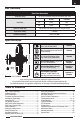
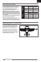
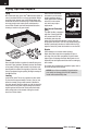
The following illustration shows the factory settings for
linkages on the control horns. After flying, carefully adjust
the linkage positions for the desired control response.
Aileron Elevator Rudder
Before the rst ights, or in the event of an accident,
make sure the ight control surfaces are centered.
Adjust the linkages mechanically if the control surfaces
are not centered. Use of the transmitter sub-trims may
not correctly center the aircraft control surfaces due to
the mechanical limits of linear servos.
1. Make sure the control surfaces are neutral when
the transmitter controls and trims are centered. The
transmitter sub-trim must be always be set to zero.
2. When needed, use a pair of pliers to carefully bend
the metal linkage (see illustration).
3. Make the U-shape narrower to make the connector
shorter. Make the U-shape wider to make the
linkage longer.
Centering Controls After First Flights
For best performance with AS3X, it is important
that excessive trim is not used. If the model requires
excessive transmitter trim (4 or more clicks of trim per
channel), return the transmitter trim to zero and adjust
the linkages mechanically so that the control surfaces
are in the flight trimmed position.
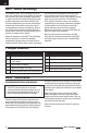
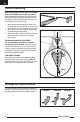
1mm Offset of Rudder
After centering the rudder, we recommend adjusting
the rudder linkage so the rudder center is 1mm right
(measured at the trailing edge of the rudder) from center
while rudder trim on your transmitter is at neutral.
Control Centering
1mm
Settings for Control Horns