
UMX F-27 Evolution BNF Basic Manual

Before the first flights, or in the event of an accident,
make sure control surfaces are centered when
the transmitter controls and trims are neutral. The
transmitter sub-trim must be set to zero.
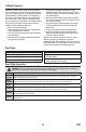
Adjust the linkages mechanically if the control surfaces
are not centered. Use of the transmitter sub-trims may
not correctly center the aircraft control surfaces due to the
mechanical limits of linear servos.
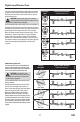
Make the U-shape narrower to make the connector shorter.
Make the U-shape wider to make the linkage longer.
NOTICE: Ultra micro linear servos are unique in that they
are calibrated to reach maximum travel at 100% travel
adjust. Increasing the value above 100% will NOT result
in more travel, but can cause the servo to lock and will
result in a crash.
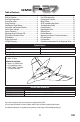
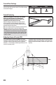
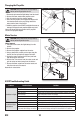
The recommended CG location is 75mm (2.95 inches)
forward from the fi rewall at the back of the fuselage. This
CG location has been determined with the included 3S
300mAh 11.1V Li-Po battery installed approximately in the
center of the battery cavity.
The battery cavity is oversized to allow for center of gravity
adjustment. Start by placing the battery in the center of the
cavity and adjust as necessary to achieve the proper center
of gravity.
6
EN
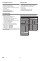
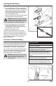
Control Horn Settings
Control Centering
Adjusting Center of Gravity (CG)
The table at the right shows the factory settings for the
elevon control horns and servo arms. Do not make changes
to the elevon linkages.
Control Horns Servo
75mm