Spitfire Mk XIV 1.
EN NOTICE All instructions, warranties and other collateral documents are subject to change at the sole discretion of Horizon Hobby, LLC. For up-to-date product literature, visit www.horizonhobby.com and click on the support tab for this product.
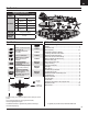
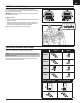
EN Box Contents Quick Start Information Transmitter Setup Dual Rates Set up your transmitter using the transmitter setup chart Hi Rate Low Rate Ail p20mm q18mm p15mm q12mm Ele 12mm 9mm Rud 25mm 18mm Flaps q=30mm Landing Takeoff q=15mm Center of Gravity (CG) 78mm back from leading edge of wing at the fuselage.
EN SAFE® Select Technology The evolutionary SAFE® Select technology can offer an extra level of protection so you can perform the first flight with confidence. No complex transmitter programming is required. Just follow the simple bind process to make the SAFE Select system active. When activated, bank and pitch limitations keep you from over-controlling and automatic self-leveling makes recovery from risky or confusing attitudes as simple as releasing the sticks.
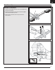
EN Model Assembly Horizontal Tail Installation 1. Slide the horizontal tail (A) into the slot in the rear of the fuselage. Ensure the control horn faces down. A 2. Secure the horizontal tail piece in place using the included screw (B). Use caution to avoid over-tightening the screw. 3. Attach the clevis to the elevator control horn (see instructions for clevis connection).
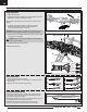
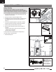
EN Model Assembly Continued Wing Installation 1. Remove the battery hatch. 2. Guide the Flaps, Retracts and Aileron servo connectors (A) through the hole (B) located in the bottom of the fuselage as shown. Tip: If needed, use hemostats or pliers to pull the servo connectors into the fuselage. 3. Connect the Flaps, Retracts and Aileron connectors to respective Y-harnesses connected to the receiver. The left and right servos can be connected to either side of a Y-harness.
EN Model Assembly Continued Propeller Installation IMPORTANT: Install the propeller after all system setups are completed to reduce the chance of accidental propeller strike. 1. Install the spinner backplate (A) and propeller (B), on the propeller shaft (C). The propeller size numbers (10.5 x 8) must face out from the motor for correct propeller operation. 2. Install the spinner nut (D) to secure the propeller into place.
EN Transmitter and Receiver Binding / Switching ON and OFF SAFE Select This product requires an approved Spektrum™ DSM2®/DSMX® compatible Switching ON SAFE Select Binding Sequence transmitter. Visit www.bindnfly.com for a complete list of approved transmitters. The aircraft has an optional SAFE Select feature, which can be switched ON or OFF easily by binding in a specific manner as described below.
EN SAFE® Select Switch Designation SAFE® Select technology can be easily assigned to any open switch on your transmitter. With this new feature, you now have the flexibility to enable or disable the technology while in flight. Mode 1 and 2 Transmitters IMPORTANT: Before assigning your desired switch, ensure that the travel for that channel is set at 100%. Assigning a switch 1. Bind the aircraft correctly to activate SAFE Select to allow the system to be assigned to a switch. 2.
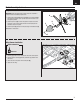
EN Battery Installation and ESC Arming A Battery Selection We recommend the E-flite 2200mAh 11.1V 3S 30C Li-Po battery (EFLB22003S30). Refer to the Optional Parts List for other recommended batteries. If using a battery other than those listed, the battery should be within the range of capacity, dimensions and weight of the E-flite Li-Po battery packs to fit in the fuselage. Be sure the model balances at the recommended CG. ® 1. Lower the throttle and throttle trim to the lowest settings.
EN Center of Gravity (CG) The CG location is measured from the leading edge of the wing at the root. This CG location has been determined with the recommended Li-Po battery (EFLB22003S30) installed all the way forward in the battery compartment. Tip: Measure the CG with the aircraft inverted. 73mm 78mm +/-3 back from leading edge of wing at the fuselage. AS3X Control Direction Test This test ensures that the AS3X® control system is functioning properly.
EN In Flight Trimming During your first flight, trim the aircraft for level flight at 3/4 throttle with flaps and gear up. Make small trim adjustments with your transmitter’s trim switches to straighten the aircraft’s flight path. 3 Seconds After adjusting trim, do not touch the control sticks for 3 seconds. This allows the receiver to learn the correct settings to optimize AS3X performance. Failure to do so could affect flight performance.
EN Post Flight 1 Disconnect the flight battery from the ESC (Required for Safety and battery life). 5 Repair or replace all damaged parts. 2 Power OFF the transmitter. 6 Store the flight battery apart from the aircraft and monitor the battery charge. 3 Remove the flight battery from the aircraft. 4 Recharge the flight battery. 7 Make note of the flight conditions and flight plan results, planning for future flights.
EN Troubleshooting Guide Problem Aircraft will not respond to throttle but responds to other controls Extra propeller noise or extra vibration Reduced flight time or aircraft underpowered Aircraft will not Bind (during binding) to transmitter Aircraft will not connect (after binding) to transmitter Possible Cause Throttle not at idle and/or throttle trim too high Reset controls with throttle stick and throttle trim at lowest setting Throttle servo travel is lower than 100% Make sure throttle servo
EN AMA National Model Aircraft Safety Code Effective January 1, 2014 A. GENERAL A model aircraft is a non-human-carrying aircraft capable of sustained flight in the atmosphere. It may not exceed limitations of this code and is intended exclusively for sport, recreation, education and/or competition. All model flights must be conducted in accordance with this safety code and any additional rules specific to the flying site. 1. Model aircraft will not be flown: (a) In a careless or reckless manner.
EN Limited Warranty What this Warranty Covers Horizon Hobby, LLC, (Horizon) warrants to the original purchaser that the product purchased (the “Product”) will be free from defects in materials and workmanship at the date of purchase.
EN Contact Information Country of Purchase United States of America Horizon Hobby Horizon Service Center (Repairs and Repair Requests) Horizon Product Support (Product Technical Assistance) Sales United Kingdom Germany France Service/Parts/Sales: Horizon Hobby Limited Horizon Technischer Service Sales: Horizon Hobby GmbH Service/Parts/Sales: Horizon Hobby SAS Phone Number/Email Address servicecenter.horizonhobby.com/ RequestForm/ productsupport@horizonhobby.com 877-504-0233 websales@horizonhobby.
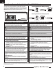
IT Replacement Parts • Ersatzteile • Pièces de rechange • Pezzi di ricambio Part # | Nummer Description Numéro | Codice Beschreibung Description Descrizione EFLP10805B Propeller: Spitfire MK XIV 1.2M Propeller: Spitfire MK XIV 1.2M MK XIV 1.2M - Hélice Elica: Spitfire MK XIV 1.2M EFL8601 Fuselage w/Hatch: MK XIV 1.2M E-flite Rumpf m. Abdeckung: MK XIV 1.2M MK XIV 1.2M - Fuselage avec trappe Fusoliera con sportello capottina: MK XIV 1.2M EFL8602 Painted Wing: MK XIV 1.
Spitfire Mk XIV 1.2m © 2016 Horizon Hobby, LLC. E-flite, AS3X, SAFE, the SAFE logo, DSM, DSM2, DSMX, the DSMX logo, Bind-N-Fly, Z-Foam, ModelMatch, Dynamite, EC3, Prophet and the Horizon Hobby logo are trademarks or registered trademarks of Horizon Hobby, LLC. The Spektrum trademark is used with permission of Bachmann Industries, Inc. Futaba is a registered trademark of Futaba Denshi Kogyo Kabushiki Kaisha Corporation of Japan.