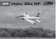
ARF ALMOST-READY-TO-FLY Habu 32x DF Instruction Manual Bedienungsanleitung Manuel d’utilisation Manuale di Istruzioni
NOTICE All instructions, warranties and other collateral documents are subject to change at the sole discretion of Horizon Hobby, LLC. For up-to-date product literature, visit horizonhobby. com and click on the support tab for this product.
HINWEIS Alle Anweisungen, Garantien und anderen zugehörigen Dokumente können im eigenen Ermessen von Horizon Hobby, LLC jederzeit geändert werden. Die aktuelle Produktliteratur finden Sie auf horizonhobby.com unter der Registerkarte „Support“ für das betreffende Produkt.
REMARQUE La totalité des instructions, garanties et autres documents est sujette à modification à la seule discrétion d’Horizon Hobby, LLC. Pour obtenir la documentation à jour, rendez-vous sur le site horizonhobby.com et cliquez sur l’onglet de support de ce produit.
AVVISO Tutte le istruzioni, le garanzie e gli altri documenti pertinenti sono soggetti a cambiamenti a totale discrezione di Horizon Hobby, LLC. Per una documentazione aggiornata sul prodotto, visitare il sito www.horizonhobby.com e fare clic sulla sezione Support per questo prodotto.
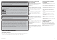
•SPECIFICATIONS•SPEZIFIKATIONEN •SPÉCIFICATIONS•SPECIFICHE •LARGE PARTS LAYOUT•BAUTEILE (OHNE KLEINTEILE)•GRANDES PIÈCES•SCHEMA DEI COMPONENTI GRANDI 42.0 in (1070mm) 8 1 412 sq in (26.6 dm2) 5 49.5 in (1250mm) 7.05–7.50 lb (3.20–3.
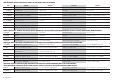
•REPLACEMENT PARTS•ERSATZTEILE•PIÈCES DE RECHANGE•PEZZI DI RICAMBIO Part English Deutsch Français Italiano 1. EFL808501 Fuselage with Hatches Rumpf mit Haube Fuselage avec capot Fusoliera con portello 2. EFL808502 Left Wing Panel Tragfläche links Aile gauche Semiala sinistra 3. EFL808503 Right Wing Panel Tragfläche rechts Aile droite Semiala destra 4.
•POWER SYSTEM•ANTRIEB•MOTORISATION•SISTEMA PROPULSIVO Part English Deutsch Français Italiano EFLM3032DFA DF32 Brushless Motor, 2150Kv E-flite BL32 Impellermotor 2150Kv Moteur brushless DF32 2150Kv Motore brushless DF32, 2150Kv EFLDF32 Delta-V® 32 80mm EDF E-flite Elektroimpeller 80mm Turbine Delta V 32 80mm EDF Delta-V 32 80mm EFLA1080B 80-Amp Pro Switch-Mode BEC Brushless ESC, EC5™ (V2) E-flite 80-Amp Pro Switch-Mode BEC Brushless Regler, EC5 (V2) Contrôleur brushless Pro 80A, switch Mode BE
Hemostat Klemme Pince Hemostat Pinzetta Hex wrench: 9/64 inch, 1.5mm, 2.5mm Inbusschlüssel: 9/64 inch, 1,5mm, 2,5mm Tournevis hexagonal : 9/64 inch, 1,5mm, 2,5mm Chiave esag.: 9/64 inch, 1,5mm, 2,5mm Hobby knife: #11 blade Hobbymesser mit # 11 Klinge Couteau : Lame numéro 11 Taglierino: #11 lama Hobby scissors Hobbyschere Ciseaux Forbici per hobby Light machine oil Nähmaschinenöl Lubrifiant Olio leggero Low-tack tape Klebeband m.
•ASSEMBLY SYMBOL GUIDE•MONTAGE SYMBOLE•GUIDE DES SYMBOLES POUR ASSEMBLAGE•GUIDA AI SIMBOLI DI ASSEMBLAGGIO Apply oil Canopy Glue Use hobby knife with #11 blade Ensure proper orientation Öl verwenden Kabinenhaubenkleber Verwenden Sie ein Hobbymesser mit # 11 Klinge Ausrichtung/Richtung sicherstellen Appliquez lubricant OIL CG Applicare olio Colle à verrière Vérifiez la bonne orientation Utilisez un Couteau: Lame numéro 11 Colla per capottine Assicurarsi dell’appropriato orientamento Usare tag
•FASTENERS•VERBINDUNGSELEMENTE•VISSERIE•ELEMENTI DI FISSAGGIO Socket Head Cap Screw Inbusschraube Vis BTR Vite a brugola Hex Nut Sechskantmutter Ecrou hexagonal Dado esagonale Self-Tapping Washer-Head Screw Schraube mit Unterlegscheibenkopf Vis auto-taraudeuse épaulée Vite autofilettante flangiata Threaded rod, threaded both ends Gewindestangen, zwei Gewinde Tringlerie filetée des 2 côtés Barretta con entrambe estremità filettate Self-Tapping Screw Selbstschneidene Schraube Vis auto-taraudeuse Vite autofile
•BEFORE STARTING ASSEMBLY •VOR DEM ZUSAMMENBAU • Remove parts from bag. • Entnehmen Sie zur Überprüfung jedes Teil der Verpackung. • Inspect fuselage, wing panels, rudder and stabilizer for damage. • If you find damaged or missing parts, contact your place of purchase. If you find any wrinkles in the covering, use a heat gun (HAN100) and covering glove (HAN150) or covering iron (HAN101) with a sealing iron sock (HAN141) to remove them.
•FLAP AND AILERON CONTROL HORN INSTALLATION•EINBAU DER QUERRUDER-UND KLAPPENHÖRNER •INSTALLATION DES GUIGNOLS DES VOLETS ET DES AILERONS•INSTALLAZIONE SQUADRETTE FLAP E ALETTONI 1 2 4 3 LL RR x7 Use medium grit sandpaper to lightly sand the control horns where they fit into the slots of the control surfaces. Prepare all the control horns at this time. Schleifen Sie mit mittleren Schleifpapier die Stellen des Ruderhornes an, die in der Fläche verklebt werden. Bereiten Sie alle Hörner vor.
5 LL RR 5 Use 5-minute epoxy to glue the control horns into the slots for the flap and aileron. Use a square to make sure the control horns are perpendicular to the control surface. Also check again to make sure the hole in the aileron control horn is directly over the hinge line. Kleben Sie die Ruderhörner mit 5 Minuten Epoxy in die Öffnungen für Klappen und Querruder ein. Nutzen Sie ein Rechteck um die Ruderhörner rechtwinklig auszurichten.
•AILERON SERVO INSTALLATION•EINBAU DER QUERRUDERSERVOS•INSTALLATION DES SERVOS D’AILERONS•INSTALLAZIONE SERVO ALETTONI 1 2 LL RR Remove the cover from the wing for the flap and aileron servos. Set the cover aside for the flap servo at this time. Nehmen Sie bitte die Abdeckungen der Querruderund Landeklappenservoschächte ab. Legen Sie die Abdeckungen zur Seite. Retirez les trappes de servos de l’aile. Rangez soigneusement les trappes des servos des volets.
4 x4 Sand the 10mm x 7mm end of the block using medium grit sandpaper. This will be the end glued to the plate in the next step. Schleifen Sie die 10mm x 7mm Fläche mit mittleren Schleifpapier an. Der Block wird im nächsten Schritt verklebt. Poncez la surface de 10x7mm avec le l’abrasif grain moyen. Cette surface sera collée à la trappe lors de la prochaine étape. Carteggiare un’estremità del blocco da 10 x 7mm che verrà poi incollato sulla piastra nel passo successivo.
8 LL RR Position the servo between the two blocks. Leave a small gap between the servo and servo cover so vibrations from the airframe are not transferred directly into the servo. Use a pencil to mark the locations for the two servo mounting screws on the blocks. Positionieren Sie das Servo zwischen die beiden Blocks. Lassen Sie einen kleinen Spalt, so dass Vibrationen des Rumpfes nicht gleich direkt auf das Servo übertragen werden können. Markieren Sie mit einem Stift die Bohrlöcher.
12 13 14 LL RR Use the screws provided with the servo and a #1 Phillips screwdriver to attach the servo to the mounting blocks. Schrauben Sie das Servo mit den mitgelieferten Schrauben und einem Phillips #1 Schraubendreher fest. Utilisez les vis fournies avec le servo et un tournevis cruciforme #1 pour fixer le servo aux blocs. Per fissare i servi ai blocchi, usare le viti fornite con essi, stringendole con un cacciavite Phillips #1.
Î The opposite end of the string will be used to pull the flap servo lead through the wing panel. Use care not to accidentally pull the wrong end of the string through the wing. 15 16 Î Die andere Seite der Schnur wird dazu genutzt das Kabel des Klappenservos durch die Tragfläche zu ziehen. Bitte achten Sie darauf nicht aus Versehen das falsche Ende des Kabels durch die Fläche zu ziehen. Î L’extrémité opposée de la ficelle sera utilisée pour tirer le câble du servo de volet à travers l’aile.
17 18 •FLAP SERVO INSTALLATION •EINBAU DER KLAPPENSERVOS •INSTALLATION DES SERVOS DE VOLETS •INSTALLAZIONE DEL SERVO DEI FLAP Î When centering the flap servo, begin by setting the throws at the transmitter to 0% for both the up and down flap positions. This is done for both 2- and 3-position flap switches. x2 M2 M x4 x4 M2 x 25 x2 Assemble the aileron linkage using the two pieces of tubing from the previous step, two M2 nuts, two metal clevises and the M2 x 25 threaded rod.
1 Prepare the flap servos by installing the rubber grommets and brass eyelets as shown in the radio or servo instructions. Center the flap servo using the radio system. Use side cutters to remove any arms from the horn that may interfere with the operation of the servo. Bereiten Sie das Klappenservo durch einschieben der Gummipuffer und Blechösen vor. Zentrieren Sie das Servo mit der Fernsteuerung.
4 LL RR 5 Use 5-minute epoxy to glue the 13mm x 10mm x 7mm hardwood block to the servo cover. Make sure to glue the 10mm x 7mm end to the surface of the plate. Use a clamp to hold the block in position until the epoxy fully cures. Nutzen Sie 5 Minuten Epoxy um den 13mm x 10mm x 7mm Block an die Abdeckung zu kleben. Achten Sie bitte darauf die 10 x 7mm Seite anzukleben. Sichern Sie den Block mit einer Klemme und lassen Sie den Kleber vollständig trocknen.
8 LL RR Use a drill and 5/64-inch (2mm) drill bit to drill the holes for the mounting screws. Use care not to enlarge the holes any larger than the drill bit. Bohren Sie mit einem 2mm Bohrer die Löcher für die Befestigungsschrauben. Bitte achten Sie darauf, dass die Löcher nicht größer als benötigt werden. Utilisez un forêt de 2mm pour percer les trous de fixation. Prenez soin de ne pas agrandir les trous. Con una punta da 2mm praticare il foro per le viti di fissaggio.
11 12 x4 Use a hobby knife with a #11 blade to cut 1/4-inch (6mm) pieces from the silicone tubing. Schneiden Sie mit einem Hobbymesser mit # 11 Klinge zwei 6mm lange Stücke vom Silikonschlauch. Utilisez un couteau de modélisme muni d’une lame #11 pour couper des morceaux de durite silicone de 6mm. LL RR Usare un coltello tagliabalsa con lama #11 per tagliare dei pezzi da 6mm da un tubetto di silicone.
14 15 LL RR LL RR Remove the tape holding the flap in position at the trailing edge of the wing. Use the radio system to center the flap servo. Connect the metal clevis to the outer hole of flap servo horn. The remaining clevis connects to the flap control horn. Adjust the length of the linkage so the flap is set to the mid/takeoff position. Once the length of the linkage has been adjusted, slide the tubing over the forks of the clevises to keep them from accidentally opening in flight.
Î Because there can be minor differences in control horn and servo positions, do not connect the linkage as described in steps 14 and 15 to the opposite flap until you have checked the throws. Doing so may cause the servo to bind in the UP position, which could cause damage to the flap servo. Î Auf Grund von kleinen Unterschieden bei den Positionen von Servo und Ruderhorn verbinden Sie noch nicht die andere Klappenseite wie in Schritt 14 und 15 beschrieben.
2 3 4 LL RR Use a 1.5mm hex wrench to remove the strut from the retract mechanism. There are setscrews on both sides of the retract mechanism that will require removal. Secure a 3-inch (76mm) servo extension to the lead on the retract mechanism using string or a commercially available connector. Lösen Sie mit einem 1.5mm Inbusschlüssel die beiden Madenschrauben die das Fahrwerksbein im Einziehfahrwerk sichern.
5 LL RR Use a hobby knife with a new #11 blade to remove the covering for the retract mechanism and landing gear assembly. Leave 1/32 inch (1mm) of covering around the inside edges. Use a trim seal tool to iron down the covering around the edges to finish the opening. Entfernen Sie mit Hobbymesser mit neuer 11 Klinge die Bespannung für den Einbau des Fahrwerk. Lassen Sie an der Innenseite 1mm von der Bespannung überstehen und bügeln diese als Finsih fest.
9 Prepare a 3/32-inch (2.5mm) drill bit by wrapping a piece of low-tack tape around the drill bit 5/8 inch (16mm) from the end of the bit. This will act as a marker so you don’t accidentally drill through the top of the wing. Kleben Sie ein Stück Isolierband auf einen 2,5mm Bohrer so dass 16mm verbleiben. Das Isolierband dient als Markierung damit sie nicht versehentlich durch die Fläche bohren. Prenez un foret de 2.
13 LL RR x2 Check the fit of the wheel on the landing gear strut. It may be necessary to use a 9/64-inch (4mm) drill bit to carefully drill the bushings so the wheel spins freely on the axle. Prüfen Sie die Passung des Rades auf der Fahrwerksstrebe. Es könnte könnte notwendig sein die Öffnung mit einem 4mm Bohrer nachzubohren, so dass das Rad frei dreht. Contrôlez l’ajustement de la roue sur la jambe de train.
•LANDING GEAR DOOR INSTALLATION•EINBAU DER FAHRWERKSTÜREN•INSTALLATION DES TRAPPES DE TRAIN•INSTALLARE IL PORTELLO DEL CARRELLO Î The installation of the landing gear doors is optional and they can be installed at any time during the life of your model. 2 3 4 Î Hinweis: Der Einbau der Fahrwerkstüren ist optional und kann auch jeder Zeit nach Fertigstellung durchgeführt werden. Î L’installation des trappes de train est facultative et peut s’effectuer à n’importe quel moment.
5 6 x4 Use a drill and 1/16-inch (1.5mm) drill bit to drill the two mounting holes in the landing gear door block. Drill the holes perpendicular to the sanded edge of the block. Bohren Sie mit einem 1,5mm Bohrer die beiden Befestigungslöcher in den Holzblock. Schleifen Sie die Fahrwerkstürblöcke so, dass Sie wie abgebildet an die Innenseite der Fahrwerkstüren passen. Arbeiten Sie hier bitte mit dem Schleifblock und mittlererem Schleifpapier. Stellen Sie beide Blöcke fertig.
9 LL RR M2 x 8 x8 10 LL RR Use a #1 Phillips screwdriver to thread an M2 x 8 self-tapping washer-head screw in each of the mounting holes in the landing gear door block. Remove the screws and place 2–3 drops of thin CA in each of the mounting holes to harden the threads. Attach the landing gear door to the strut using the screws and a #1 Phillips screwdriver. Retract the landing gear using the radio system. This will set the correct angle for the landing gear door against the wing.
•WING SPAR INSTALLATION•EINBAU DES TRAGFLÄCHENVERBINDER•INSTALLATION DE LA CLÉ D’AILE•INSTALLAZIONE DEL LONGHERONE ALARE 1 2 3 Schieben Sie den Verschlusshebel nach hinten und heben die Kabinenhaube vom Rumpf. Die Kabinenhaube wird vorne von zwei Stiften im Rumpf gehalten. Legen Sie die Kabinenhaube zur Seite, dass sie nicht beschädigt wird. Poussez le loquet vers l’arrière et soulevez la verrière du fuselage. La verrière est maintenue par 2 tétons à l’avant.
5 6 7 8 t5PQt0CFO t%FTTVTt1BSUF TVQFSJPSF /PU UP TDBMF /JDIU NBUBCTHFUSFV 1BT Ë MhÏDIFMMF /PO JO TDBMB LL RR Locate the carbon wing spar. Use a straight edge or rest the joiner on a flat surface. The top of the joiner is flat, while the bottom will have a slight angle as shown in the drawing. This is necessary to conform to the dihedral built into the model. Nehmen Sie den Flächenverbinder zur Hand. Legen Sie ihn auf eine gerade Platte.
9 LL RR 10 M2.5 x 10 Use a #1 Phillips screwdriver to start the M2.5 x 10 sheet metal screws that will secure the forward wing pin in the fuselage. Remove the wing and spar from the fuselage. Apply a thin coat of petroleum jelly to the fuselage around the wing socket. This will keep you from accidentally gluing the wing to the fuselage during the following procedure. Drehen Sie mit einem # Philips Schraubendreher die M2.5 x10 Metallschrauben ein, die die vorderen Tragflächensitfte halten.
Î Before mixing any epoxy, make sure to read through and understand the following steps. It is important to perform these steps before the epoxy fully cures. 12 13 14 Î Bitte lesen Sie zum Verständnis die nächsten Schritte vor dem Anmischen des 15 Minuten Epoxy durch, da sie während der Aushärtezeit durchgeführt werden müssen. Î Avant d’effectuer le mélange de la colle Epoxy, lisez les étapes suivantes. Il est important d’effectuer ces tâches avant le séchage de la colle Epoxy.
15 •RETRACTABLE NOSE GEAR INSTALLATION•EINBAU EINZIEHBARES BUGFAHRWERK •INSTALLATION DE LA JAMBE RÉTRACTABLE DE NEZ•INSTALLAZIONE DEL CARRELLO ANTERIORE 1 2 3 LL RR Use the radio system to lower the main landing gear. Check that the main wheels are parallel to the fuselage centerline. If not, it may be necessary to lightly file the flat areas on the landing gear wire to correct for any misalignment.
4 5 6 Use the radio system to move the nose gear retract to the UP position. Use a 1.5mm hex wrench to loosen the screw on the steering arm and wheel collar to remove the strut from the mechanism. Fahren Sie mit der Fernsteuerung das Bugrad ein. Lösen Sie mit einem 1,5mm Inbusschlüssel die Madenschraube am Lenkarm und Stellring um das Fahrwerksbein ab zu nehmen. Utilisez votre radio pour placer le mécanisme en position HAUTE. Utilisez une clé btr de 1.
7 8 M2 M x2 x2 9 M2 x 60 x1 Connect the clevis without the tubing to the steering arm of the nose gear assembly. Schließen Sie den Gabelkopf ohne Schlauch an den Steuerarm des Bugfahrwerks an. Use a hobby knife with a #11 blade to cut 1/4-inch (6mm) piece from the silicone tubing. Schneiden Sie mit einem Hobbymesser und 11 Klinge ein 6mm langes Schlauchstück ab. Utilisez un couteau de modélisme muni d’une lame #11 pour couper des morceaux de durite silicone de 6mm.
10 11 12 13 M3 x 8 x4 Secure the nose gear assembly in the fuselage using four M3 x 8 socket head screws and a 2.5mm hex wrench. Verschrauben Sie das Bugfahrwerk im Rumpf mit den vier M3 x8 Schrauben und einem 2.5mm Inbusschlüssel. Fixez le mécanisme dans le fuselage en utilisant 4 vis M3x8 et une clé BTR de 2.5mm. Fissare il carrello anteriore alla fusoliera con 4 viti a brugola da M3x8mm. With the radio system on and the steering servo connected to the receiver, center the servo.
13 14 15 Replacez le bras sur le servo et contrôlez que la direction est bien au neutre comme le servo. Ajustez la longueur de la tringlerie pour affiner le réglage. Une fois le réglage effectué, serrez les 2 écrous M2 contre les chapes pour éviter leur desserrage à cause des vibrations. Glissez le morceau de durites silicone sur les fourches des chapes et fixez le bras au servo en utilisant un tournevis cruciforme #1.
16 17 M3.5 Check the fit of the wheel on the landing gear strut. It may be necessary to use a 9/64-inch (4mm) drill bit to carefully drill the bushings so the wheel spins freely on the axle. Prüfen Sie die Passung des Rades auf der Fahrwerksstrebe. Es könnte könnte notwendig sein die Öffnung mit einem 4mm Bohrer nachzubohren, so dass das Rad frei dreht. Contrôlez l’ajustement de la roue sur la jambe de train.
•RUDDER CONTROL HORN AND HINGING•SEITENRUDERHORN UND SCHARNIERE•INSTALLATION DE LA GOUVERNE DE DÉRIVE•SQUADRETTA TIMONE E CERNIERE 1 2 3 Separate the rudder from the fin and set the hinges aside. Ziehen Sie das Seitenruder von der Finne und legen die Scharniere zur Seite. Retirez la gouverne de la dérive et mettez les charnières de coté. LL RR Carefully cut the decal down the centerline of the hinge gap using a hobby knife and a new #11 blade.
4 Remove the control horns from the rudder. Apply low-tack tape around the slot for the control horn. Position the tape so it is 1/32-inch (1mm) away from the sides of the slot, as well as from the marks made in the previous step. Nehmen Sie das Ruderhorn vom Ruder ab. Kleben Sie Kreppband um den Schlitz des Horns im Ruder. Positionieren Sie das Tape so, dass es 1mm vom Schlitz und den Markierungen vom letzten Schritt entfernt ist. Retirez le guignol de la gouverne.
7 x3 8 9 x3 Fit the rudder hinges. The hinge pin will align with the hinge line of the rudder. Position the hinge perpendicular to the hinge line. Check that it can move freely. Passen Sie die Scharniere ein. Das Scharnier muß mit der Scharnierlinie des Ruders fluchten. Richten Sie das Scharnier rechtwinklig zur Scharnierlinie aus. Prüfen Sie dass es sich frei bewegen kann. Mettre en place les charnières de la dérive. L’axe de la charnière sera alignée avec la ligne de la charnière de dérive.
10 x3 5 Once the epoxy has cured, check the operation of the hinges. Remove any epoxy that may be interfering with the hinges. Apply epoxy to the hinges and into the holes in the fin. Prüfen Sie nachdem das Epoxy getrocknet die Funktion der Scharniere. Entfernen Sie alles an Epoxy was die Funktion der Scharniere beeinflußt. Streichen Sie Epoxy an die Scharniere und in die Löcher an der Finne. Une fois le séchage terminé, contrôlez le libre rotation des charnières.
•RUDDER SERVO INSTALLATION•EINBAU DES SEITENRUDERSERVOS•INSTALLATION DU SERVO DE DIRECTION•INSTALLAZIONE SERVO DEL TIMONE 1 2 Secure an 12-inch (300mm) servo extension to the rudder servo using string or a commercially available connector. Sichern Sie eine 300mm lange Servokabelverlägerung mit Garn oder einem Verbinder. Center the rudder servo using the radio system.
4 Use a #1 Phillips screwdriver to remove the two M2 x 8 self-tapping screws that secure the rudder servo plate to the rudder servo mounts. Set the screws and plate aside to be installed in the next step. Schrauben Sie mit einem #1 Phillips Schraubendreher die beiden Schrauben des Seitenruderservohalters los und legen den Halter zur Seite. Utilisez un tournevis cruciforme #1 pour retirer les 2 vis M2x8 qui maintiennent la platine de fixation au fuselage. Rangez soigneusement la platine et les vis.
8 Route the rudder servo lead through the fuselage and formers as shown. The lead will be routed under the fiberglass intake inside the fuselage. Führen Sie die Servokabel durch den Rumpf und die Öffnungen in den beiden Spanten nach vorne Richtung Cockpit. Guidez le câble du servo de dérive dans le fuselage et au travers du couple comme sur l’illustration. Le câble doit être glissé sous l’entrée d’air en fibre de verre.
11 12 Retirez l’adhésif de masquage qui maintien la gouverne de dérive en position. Installez la tringlerie entre le servo et la gouverne. Coudez la tringlerie afin qu’elle n’entre pas en contact avec le fuselage en fin de course. Ajustez la longueur de la tringlerie afin que la dérive soit centrée quand le servo est au neutre.
3 4 LL RR LL RR Remove the control horns from the elevator. Apply lowtack tape around the slot for the control horn. Position the tape so it is 1/32 inch (1mm) away from the sides of the slot, as well as from the marks made in the previous step. After around 3 minutes, before the epoxy cures, carefully remove the tape from around the control horn. Pull the tape away from the horn, being careful not to disturb the position of the control horn.
•STABILIZER SPAR INSTALLATION•EINBAU HÖHENLEITWERKSSPANT •INSTALLATION DE LA CLÉ DE STABILISATEUR•INSTALLAZIONE DEL LONGHERONE STABILIZZATORE 1 2 Î Cut a 1/2-inch (13mm) piece of silicone tubing and slide it on a 2.5mm hex wrench. Place the 3mm screw in the tubing against the hex wrench so it can be installed to secure the stabilizer spars. Î Schneiden Sie ein 13mm langes Stück vom Silikonschlauch ab und schieben es auf einen 2,5mm Inbusschlüssel.
3 LL RR Use a felt-tipped pen to mark the edge of the fuselage on the spar. Markieren Sie mit einem Faserstift die Stelle wo der Holm aus dem Rumpf austritt. Utilisez un feutre pour tracer un repère sur la clé au niveau du fuselage. Usare un pennarello per segnare i bordi della fusoliera sul longherone. 4 LL RR Remove the spar from the fuselage using a 2.5mm hex wrench. Check the fit of the spar in the stabilizer. It should easily slide in up to the line drawn on the spar in the previous step.
7 8 9 Equal distance DE Égale distance Egual distanza Attach the wing panels to the fuselage using a 9/64inch hex wrench. Stand back 8–10 feet (2–3 meters) and check that the stabilizers are positioned an equal distance from the wing. If not, the spars may need to be sanded slightly to correct any alignment issues. Schrauben Sie die beiden Tragflächen mit einem 9/64 Inbusschlüssel an den Rumpf.
10 11 12 •ELEVATOR SERVO INSTALLATION •EINBAU DES HÖHENRUDERSERVOS •INSTALLATION DU SERVO DE PROFONDEUR •INSTALLAZIONE DEL SERVO ELEVATORE LL RR 15 Use an epoxy brush to apply epoxy to the front, back, top and bottom of the spar where it fits into the stabilizer. Streichen Sie mit einem Pinsel Epoxy auf die Seite des Holm der in das Höhenruder geht. Appliquez la colle Epoxy sur toutes les faces de la partie de la clé de stabilisateur qui entre dans le stabilisateur.
2 Remove the arm from the elevator servos. The elevator linkage will be connected to the hole in the servo that is 3/8 inch (10mm) from the center of the arm as illustrated in the photo above. Remove any portion of the arm extending past the hole so it doesn’t rub against the intake when the horn is installed. Attach the horns back on the elevator servos. Die Anlenkung wird in das Loch des Servoarmes gesteckt dass 10mm von der Mitte entfernt ist.
5 6 x4 Use a hobby knife with a #11 blade to cut 1/4-inch (6mm) pieces from the silicone tubing. Schneiden Sie mit einem Hobbymesser und 11 Klinge ein 6mm langes Schlauchstück ab. Utilisez un couteau de modélisme muni d’une lame #11 pour couper des morceaux de durite silicone de 6mm. Usare un coltello tagliabalsa con lama #11 per tagliare un pezzo da 6mm da un tubetto di silicone. M2 x 8 7 x2 M2 M x1 M2 x 412 x1 x1 Slide the piece of silicone tubing on a metal clevis.
8 9 LL RR Slide the pushrod into the tube from the rear of the fuselage. Schieben Sie das Gestänge von hinten in das Bowdenzugröhrchen ein. Glissez la tringlerie dans la gaine par l’arrière du fuselage. Inserire la barretta nel tubetto dal retro della fusoliera. Slide the piece of silicone tubing on a metal clevis. Thread an M2 nut then the clevis on the end of the pushrod inside the fuselage. Connect the clevis to the elevator servo horn. Connect the clevis to the elevator control horn.
•FAN INSTALLATION•IMPELLER EINBAU •INSTALLATION DE LA TURBINE•INSTALLAZIONE DELLA VENTOLA 10 1 Mounting lug Befestigungslasche Patte de fixation Aletta di montaggio Fan bottom (fuselage top) Impeller Unterseite (Rumpf oben) Dessous de la turbine (Dessus du fuselage) Parte inferiore della ventola (superiore della fusoliera) Label Etikett Etiquette Etichetta Mounting lug Befestigungslasche Patte de fixation Aletta di montaggio M2 Fan centerline Impeller Mittellinie Ligne centrale de la turbine Linea
2 Mount the motor in the fan unit using the screws included with the motor. Make sure the motor wires are located away from the label as shown. Montieren Sie den Motor mit den Schrauben aus dem Lieferumfang. Bitte stellen Sie sicher, dass die Motorkabel vom Etikett wie dargestellt wegzeigen. 3 5 Pass the wires through the fan fairing. Remove the fan adapter by loosening the fan nut. Führen Sie die Kabel aus der Verkleidung. Nehmen Sie den Impelleradapter mit lösen der Mutter ab.
8 9 10 Measure back 1/2 inch (13mm) and 15/8 inch (42mm) from where the edge of the fan housing fits in the tube. Use these lines and those that aligned with the fan fairing to draw a rectangle on the tube. Carefully draw an airfoil shape that matches the fan fairing in the rectangle. Use a square and pencil to draw two lines along on the outside of the fan housing to indicate the location of the fan fairing.
11 Use hobby scissors to trim the exhaust tube for the fan fairing. Slot the exhaust tube so it can be slid over the fan fairing. Schneiden Sie mit einer Schere einen Schlitz in das Schubrohr und schneiden dann die Form des Halters aus. Sie können so das Schubrohr auf das Gehäuse schieben. Utilisez des ciseaux à Lexan pour découper le passage du carénage. Effectuez une rainure dans le tube afin de pouvoir le passer par dessus le carénage.
•EXHAUST TUBE AND SPEED CONTROL INSTALLATION •MONTAGE SCHUBROHR UND REGLER/ESC •INSTALLATION DU TUBE DE TUYÈRE ET DU CONTRÔLEUR. •INSTALLAZIONE DEL TUBO DI SCARICO E DEL REGOLATORE DI VELOCITA’ 15 Use a #1 Phillips screwdriver to thread an M3 x 10 self-tapping screw (included with the fan unit) into the four holes for mounting the fan unit. Remove the screws, then place 2–3 drops of thin CA in each hole to harden the surrounding wood. Secure the fan unit in the fuselage using the screws.
3 Position the exhaust tube so it overlaps onto the fan assembly. Use clear tape to secure the thrust tube to the fan housing. Positionieren Sie den Schlitz so, dass er den Halter überlappt. Orientez le tube de manière a glissez les câbles et le carénage au travers de l’ouverture. Utilisez de l’adhésif transparent pour fixer la tuyère à la turbine. Posizionare il tubo di scarico in modo che si sovrapponga al gruppo ventola. Usare del nastro trasparente per fissare il tubo all’alloggiamento della ventola.
8 •RECEIVER INSTALLATION•EMPFÄNGEREINBAU•INSTALLATION DU RÉCEPTEUR•INSTALLAZIONE DEL RICEVITORE Remove the backing from the hook and loop tape to mount the speed control inside the fuselage. Make sure to secure the switch inside the fuselage where it can be easily accessed using double-dated tape. Ziehen Sie das Abdeckpapier des Klettbandes vom Regler ab und befestigen ihn im Rumpf. Stellen Sie sicher, dass der Schalter an einer gut zu erreichenden Stelle mit Doppelklebeband im Rumpf plaziert ist.
4 LL RR Route the flap extension into the hole forward of the left elevator servo. The extension will go under the intake inside the fuselage. The aileron extension is routed through the hole on the right side of the fuselage. Führen Sie die Klappenverlängerung in das vordere Loch bei dem linken Höhenruderservo. Die Verlängerung des Querruders wird durch das Loch auf der rechten Seite des Rumpfes geführt. Guidez la rallonge des volets dans l’ouverture située devant le servo de profondeur gauche.
8 •MOTOR BATTERY INSTALLATION•EINBAU DES ANTRIEBSAKKU •INSTALLATION DE LA BATTERIE•INSTALLAZIONE BATTERIA DEL MOTORE Secure the battery tray back in the fuselage. Schrauben Sie den Akkuhalter in den Rumpf. Replacez le support de batterie dans le fuselage. Fissare il supporto della batteria indietro nella fusoliera. 1 3 2 Secure the battery in the fuselage using the hook and loop strap. Make sure the strap is not pinching any of the servo leads on the bottom side of the battery tray.
•CANOPY AND PILOT INSTALLATION•MONTAGE COCKPIT UND PILOT•INSTALLATION DU PILOTE ET DE LA VERRIÈRE•INSTALLAZIONE DELLA CAPOTTINA E DEL PILOTA 1 Locate the cockpit interior and use hobby scissors to trim the interior along the inscribed line. Trim the interior a little outside the line so it can be trimmed to fit to the canopy. Beschneiden Sie das Cockpit an der geformten Linie. Schneiden Sie ausserhalb der Linie so dass das Cockpit mit der Haupe angepaßt werden kann.
5 Use clear tape to secure the interior inside the canopy. Sichern Sie das Innenteil mit einem Stück Tesafilm. Utilisez de l’adhésif transparent pour fixer l’habillage de cockpit à l’intérieur de la verrière. Per fissare l’interno alla capottina usare del nastro adesivo trasparente.
•CENTER OF GRAVITY •DER SCHWERPUNKT •CENTRE DE GRAVITÉ •CENTRO DI GRAVITA’ (BARICENTRO) An important part of preparing the aircraft for flight is properly balancing the model. Ein sehr wichtiger Teil in der Flugvorbereitung ist es das Flugzeug richtig auszubalancieren. Une des étapes importantes de la préparation d’un modèle est son équilibrage. Un punto importante per preparare l’aereo al volo è quello di fare un centraggio corretto. 1.
•CONTROL THROWS •RUDERAUSSCHLÄGE 1. Turn on the transmitter and receiver of your model. Check the movement of the rudder using the transmitter. When the stick is moved to the right, the rudder should also move right. Reverse the direction of the servo at the transmitter if necessary. 1. Schalten Sie den Sender und Empfänger ihres Modells ein. Prüfen Sie die Seitenruderaussschläge mit dem Sender. Bewegen Sie den Seitenruderstick nach rechts, sollte sich das Ruder auch nach rechts bewegen.
•DÉBATTEMENTS •CORSE DEI COMANDI 1. Mettez l’émetteur et le récepteur sous tension. Contrôlez les mouvements de la dérive en utilisant votre émetteur. Quand le manche est vers la droite, la dérive doit s’orienter vers la droite. Inversez la direction du servo à l’émetteur si nécessaire. 1. Accendere trasmettitore e ricevitore del modello. Controllare i movimenti del timone agendo sul trasmettitore. Quando lo stick va a destra, anche il timone deve andare a destra.
•PREFLIGHT CHECKLIST •VORFLUGKONTROLLE •CHECKLIST D’AVANT VOL • • • • • • • 74 Charge the transmitter, receiver and motor battery for your airplane. Use the recommended charger supplied with your radio system. Follow the instructions provided with the radio. Charge the radio system the night before each flying session. Charge the transmitter and receiver batteries using only included or manufacturer-recommended chargers. Follow all manufacturer’s instructions for your electronic components.
•DAILY FLIGHT CHECKS •TÄGLICHER FLUG CHECK •CONTRÔLES SYSTÉMATIQUES •CONTROLLI DI VOLO GIORNALIERI • • • • Check the battery voltage of the transmitter battery. Do not fly below the manufacturer’s recommended voltage. To do so can crash your aircraft. When you check these batteries, ensure you have the polarities correct on your expanded scale voltmeter. • • • • • Achten Sie bei dem Test darauf, dass die Polarität auf dem Voltmeter richtig angezeigt wird.
•LIMITED WARRANTY What this Warranty Covers Limitation of Liability Inspection or Services Non-Warranty Service Horizon Hobby, LLC (“Horizon”) warrants to the original purchaser that the product purchased (the “Product”) will be free from defects in materials and workmanship at the date of purchase.
•GARANTIE UND SERVICE INFORMATIONEN Warnung Ein ferngesteuertes Modell ist kein Spielzeug. Es kann, wenn es falsch eingesetzt wird, zu erheblichen Verletzungen bei Lebewesen und Beschädigungen an Sachgütern führen. Betreiben Sie Ihr RC-Modell nur auf freien Plätzen un beachten Sie alle Hinweise der Bedienungsanleitung des Modells wie auch der Fernsteuerung. Garantiezeitraum Exklusive Garantie ¬ Horizon Hobby LLC (Horizon) garantiert, dass das gekaufte Produkt frei von Materialund Montagefehlern ist.
•GARANTIE ET RÉPARATIONS Durée de la garantie Garantie exclusive - Horizon Hobby, LLC (Horizon) garantit que le Produit acheté (le « Produit ») sera exempt de défauts matériels et de fabrication à sa date d’achat par l’Acheteur. La durée de garantie correspond aux dispositions légales du pays dans lequel le produit a été acquis. La durée de garantie est de 6 mois et la durée d’obligation de garantie de 18 mois à l’expiration de la période de garantie.
•GARANZIA Periodo di garanzia Limiti di danno Manutenzione e riparazione La garanzia esclusiva - Horizon Hobby, LLC, (Horizon) garantisce che i prodotti acquistati (il “Prodotto”) sono privi di difetti relativi ai materiali e di eventuali errori di montaggio. Il periodo di garanzia è conforme alle disposizioni legali del paese nel quale il prodotto è stato acquistato. Tale periodo di garanzia ammonta a 6 mesi e si estende ad altri 18 mesi dopo tale termine.
•WARRANTY AND SERVICE CONTACT INFORMATION•GARANTIE UND SERVICE KONTAKTINFORMATIONEN •COORDONNÉES DE GARANTIE ET RÉPARATIONS•GARANZIA E ASSISTENZA INFORMAZIONI PER I CONTATTI Country of Purchase Horizon Hobby Horizon Service Center (Repairs and Repair Requests) United States of America Horizon Product Support (Product Technical Assistance) servicecenter.horizonhobby.com/RequestForm/ www.quickbase.com/db/ bghj7ey8c?a=GenNewRecord 888-959-2305 sales@horizonhobby.co.
•ACADEMY OF MODEL AERONAUTICS NATIONAL MODEL AIRCRAFT SAFETY CODE Effective January 1, 2014 A. GENERAL: A model aircraft is a non-humancarrying aircraft capable of sustained flight in the atmosphere. It may not exceed limitations of this code and is intended exclusively for sport, recreation, education and/or competition. All model flights must be conducted in accordance with this safety code and any additional rules specific to the flying site. 1.
EFL Habu 32x DF
EFL Habu 32x DF 83
© 2014 Horizon Hobby, LLC. E-flite, AS3X, Delta-V, EC5, Dynamite, Prophet, Precept, DSMX, the DSMX logo and the Horizon Hobby logo are trademarks or registered trademarks of Horizon Hobby, LLC. The Spektrum trademark is used with permission of Bachmann Industries, Inc. All other trademarks, service marks and logos are the property of their respective owners.