
User Manual


9
EN
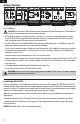
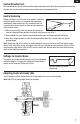
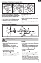
Service of Power Components
Disassembly
•Holdtheshaft
B
using needle-nose pliers
or hemostats.
•Removethepropeller
A
by turning it
counterclockwise on the threaded shaft
B
•Holdthenut
E
on the shaft
B
using needle-
nose pliers or hemostats.
•Turnthespurgearontheshaft
B
clockwise to remove the nut.
•Gentlypulltheshaft
B
from the gearbox
D
.
Note: Make sure bushings
C
are not lost when
gear shaft is removed from the gearbox.
Assembly
•Turna130mmx70mmpropeller
A
clockwise
on the shaft.
Note: Numbers on the propeller must face out
from fuselage for correct propeller operation.
•Installtheshaft
B
in the gearbox
D
.
•Holdthenut
E
on the back of the
shaft
B
.
•Turnthespurgear
B
counterclockwise until
the nut is tightly installed on the shaft
B
.
Note: Carefully align gear shaft
B
with pinion
gear on motor
F
.
Note: Avoid disconnecting motor from receiver.
When motor is connected to the receiver, make
sure wire connectors are correctly aligned so
motor turns the propeller in the correct direction.
CAUTION: DO NOT handle propeller parts while the flight battery is connected.
Personal injury could result.
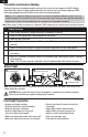
SFGshelpwithknife-edgeying.Theyaddside
force in all attitudes which greatly increases rudder
authority making a variety of 3D aerobatics pos-
sible. However, installation is optional.
1.TurnSFGsoitisnearatinrelationtothewing.
2.LowerpartofSFGwithpre-cutslotmustgo
under carbon wing supports.
3.PutchannelinSFGonwing.
4.TurnSFGcarefullysorearsupportgoesinslotin
SFG(seeillustration).
5.AttachSFGtowingandcarbonsupportsusing
foam-safe CA.
6.AttachanSFGonotherwingusinginstructions
above.
Installation of Side Force Generator (SFG)
B
D
F
A
E
C
Note: Wiring not shown