
User Manual


EN
Model Assembly Continued
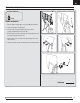
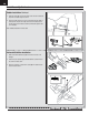
Rudder Installation Continued
7. Attach the Z-bend (E) of the control linkage to the servo arm’s outermost
hole, with the Z-bend facing in as shown.
8. Ensure the rudder servo arm is in the correct position and the rudder is
centered, then snap the ball link (F) onto the ball of the rudder control
horn (G). Ensure that the rudder is centered; remove and adjust the ball
link if necessary.
When needed, disassemble in reverse order.
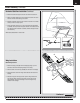
Horizontal Stabilizer Installation
1. Slide the horizontal stabilizer tube (A) into the hole in the rear of the
fuselage.
2. Install the 2 piece (left and right) horizontal stabilizer as shown. Ensure
the control horn faces down.
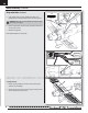
3. Secure the 2 piece tail in place with 2 screws (B) in the bottom of each
side of the horizontal tail.
G
E
F
A
B
15mm (2)
6