
EFL4850 Commander mPd Manual

EN
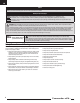
Model Assembly Continued
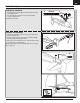
Wing Installation
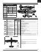
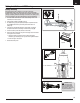
IMPORTANT: The intergrated servo connectors are in the wing and fuselage.
Ensure that they slide together correctly.
1. Secure the wing halves into position using the included 4 screws. Use the
4 x 20 screw (A) for rear holes and 4 x 25 screw (B) for the front holes.
Disassemble in reverse order.
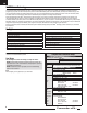
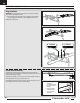
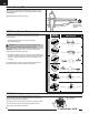
Control Surface Centering
After assembly and transmitter setup, confi rm that the control surfaces are
centered. If the control surfaces are not centered, mechanically center the control
surfaces by adjusting the linkages.
If adjustment is required, turn the ball link on the linkage to change the length of
the linkage between the servo arm and the control horn.
After binding a transmitter to the aircraft receiver, set the trims and sub-trims to
0, then adjust the ball links to center the control surfaces.
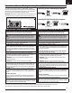
4 X 25mm
B
4 X 20mm
A
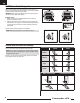
• Turn the linkage
clockwise or
counterclockwise until
the control surface is
centered.
• Attach the linkage
to the servo arm or
control horn after
adjustment.
6
Commander mPd