Commander mPd Instruction Manual Bedienungsanleitung Manuel d’utilisation Manuale di Istruzioni SAFE® Select Technology, Optional Flight Envelope Protection
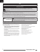
EN NOTICE All instructions, warranties and other collateral documents are subject to change at the sole discretion of Horizon Hobby, LLC. For up-to-date product literature, visit www.horizonhobby.com and click on the support tab for this product.
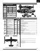
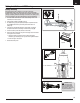
EN Box Contents Quick Start Information Transmitter Setup Dual Rates Set up your transmitter using the transmitter setup chart Hi Rate Low Rate Ail 25mm 25mm 18mm 18mm Ele 20mm 15mm Rud 50mm 40mm Flaps =40mm Landing Takeoff =20mm Center of 88mm +/-3mm back from leading edge of wing at the fuselage.
EN SAFE® Select Technology The evolutionary SAFE® Select technology can offer an extra level of protection so you can perform the first flight with confidence. No complex transmitter programming is required. Just follow the simple bind process to make the SAFE Select system active. When activated, bank and pitch limitations keep you from over-controlling and automatic self-leveling makes recovery from risky or confusing attitudes as simple as releasing the sticks.
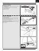
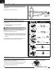
EN Model Assembly Landing Gear Installation 1. Install the landing gear assembly (A) into the pocket located at the bottom of the fuselage as shown. B 4X 40mm B 2. Secure the landing gear into place with the 2 included screws (B) (4 x 40mm screws) as shown. A Disassemble in reverse order. Horizontal Tail Installation 1. Slide the horizontal tail (A) into the slot in the rear of the fuselage. Ensure the control horn faces down. 2.
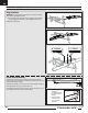
EN Model Assembly Continued Wing Installation IMPORTANT: The intergrated servo connectors are in the wing and fuselage. Ensure that they slide together correctly. 1. Secure the wing halves into position using the included 4 screws. Use the 4 x 20 screw (A) for rear holes and 4 x 25 screw (B) for the front holes. Disassemble in reverse order. A 4 X 20mm B 4 X 25mm Control Surface Centering After assembly and transmitter setup, confirm that the control surfaces are centered.
EN Transmitter and Receiver Binding / Switching ON and OFF SAFE Select This product requires an approved Spektrum™ DSM2®/DSMX® compatible transmitter. Visit www.bindnfly.com for a complete list of approved transmitters. Switching ON SAFE Select Binding Sequence The aircraft has an optional SAFE Select feature, which can be switched ON or OFF easily by binding in a specific manner as described below.
EN SAFE® Select Switch Designation SAFE® Select technology can be easily assigned to any open switch (2 or 3 position) on your transmitter. With this new feature, you now have the flexibility to enable or disable the technology while in flight. Mode 1 and 2 Transmitters IMPORTANT: Before assigning your desired switch, ensure that the travel for that channel is set at 100% in both direction. Assigning a switch 1. Bind the aircraft correctly to activate SAFE Select.
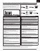
EN Battery Installation and ESC Arming Battery Selection We recommend the E-flite® 2200mAh 11.1V 3S 30C Li-Po battery (EFLB22003S30). Refer to the Optional Parts List for other recommended batteries. If using a battery other than those listed, the battery should be within the range of capacity, dimensions and weight of the E-flite Li-Po battery packs to fit in the fuselage. Be sure the model balances at the recommended CG. A 1. Lower the throttle and throttle trim to the lowest settings.
EN Center of Gravity (CG) The CG location is measured from the leading edge of the wing at the root. This CG location has been determined with the recommended Li-Po battery (EFLB22003S300). Tip: Measure the CG with the aircraft inverted. 88mm +/- 3mm back from leading edge of wing at the fuselage. AS3X Control Direction Test This test ensures that the AS3X® control system is functioning properly. Assemble the aircraft and bind your transmitter to the receiver before performing this test.
EN Flying Tips and Repairs Consult local laws and ordinances before choosing a flying location. Range Check your Radio System Before you fly, range check the radio system. Refer to your specific transmitter instruction manual for range test information. Oscillation Once the AS3X system is active (after advancing the throttle for the first time), you will normally see the control surfaces react to aircraft movement.
EN Post Flight 1. Disconnect the flight battery from the ESC (Required for Safety and battery life). 2. Power OFF the transmitter. 3. Remove the flight battery from the aircraft. 4. Recharge the flight battery. 5. Repair or replace all damaged parts. 6. Store the flight battery apart from the aircraft and monitor the battery charge. 7. Make note of the flight conditions and flight plan results, planning for future flights.
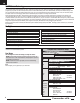
EN Troubleshooting Guide Problem Possible Cause Throttle not at idle and/or throttle trim too high Throttle servo travel is lower than 100% Throttle channel is reversed Motor disconnected from ESC Damaged propeller and spinner, collet or motor Extra propeller noise Propeller is out of balance or extra vibration Prop nut is too loose Flight battery charge is low Reduced flight time Propeller installed backwards or aircraft underFlight battery damaged powered Flight conditions may be too cold Battery capaci
EN AMA National Model Aircraft Safety Code Effective January 1, 2014 B. RADIO CONTROL A. GENERAL 1. All pilots shall avoid flying directly over unprotected people, vessels, vehicles or structures and shall avoid endangerment of life and property of others. A model aircraft is a non-human-carrying aircraft capable of sustained flight in the atmosphere. It may not exceed limitations of this code and is intended exclusively for sport, recreation, education and/or competition.
EN Limited Warranty What this Warranty Covers Horizon Hobby, LLC, (Horizon) warrants to the original purchaser that the product purchased (the “Product”) will be free from defects in materials and workmanship at the date of purchase.
EN Contact Information Country of Purchase United States of America Horizon Hobby Horizon Service Center (Repairs and Repair Requests) Horizon Product Support (Product Technical Assistance) Sales United Kingdom Germany France Service/Parts/Sales: Horizon Hobby Limited Horizon Technischer Service Sales: Horizon Hobby GmbH Service/Parts/Sales: Horizon Hobby SAS Phone Number/Email Address servicecenter.horizonhobby.com/ RequestForm/ productsupport@horizonhobby.com 877-504-0233 websales@horizonhobby.
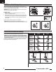
Replacement Parts • Ersatzteile • Pièces de rechange • Pezzi di ricambio Part # | Nummer Numéro | Codice EFL4821 EFL4822 EFL4823 EFL4824 EFL4825 EFL4826 EFL4827 EFL4828 EFL4829 EFL4830 EFL4831 EFL4832 EFL4833 EFL4834 EFL4835 EFL4836 EFLP12080E2 EFLM4015C EFLA1045 SPMSA330 SPMAR636A Description Beschreibung Painted Fuselage: Commander mPd 1.4m Painted Wing Set Left & Right: Commander mPd 1.4m Horizontal Tail Set Left&Right: Commander mPd 1.4m Hatch Painted with Pilot: Commander mPd 1.
Optional Parts • Optionale Bauteile • Pièces optionnelles • Pezzi opzionali Part # | Nummer Description Numéro | Codice EFLA250 Park Flyer Tool Assortment, 5 pc Beschreibung Description Park Flyer Werkzeugsortiment, 5 teilig Assortiment d'outils park flyer, 5pc EFLAEC302 EC3 Battery Connector, Female (2) EC3 Akkukabel, Buchse (2) Prise EC3 femelle (2pc) EFLAEC303 EC3 Device/Battery Connector, Male/ Female 11.1V 3S 30C 2200MAH Li-Po 11.1V 3S 30C 2500MAH Li-Po 11.1V 3S 30C 3000MAH Li-Po 11.
Commander mPd © 2017 Horizon Hobby, LLC. E-flite, Commander MPD, DSM2, DSMX, Bind-N-Fly, BNF, Plug-N-Play, AS3X, SAFE, the SAFE logo, ModelMatch, Passport, Prophet, EC3, and the Horizon Hobby logo are trademarks or registered trademarks of Horizon Hobby, LLC. The Spektrum trademark is used with permission of Bachmann Industries, Inc. All other trademarks, service marks and logos are property of their respective owners. US 8,672,726. US 9,056,667. Other patents pending. http://www.e-fliterc.