
User's Manual
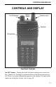

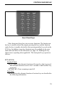
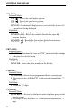
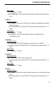

Table Of Contents
- SAFETY INFORMATION
- IMPORTANT OPERATING INFORMATION
- QUICK REFERENCE GUIDE
- FEATURES
- CONTROLS AND DISPLAY
- BASIC OPERATION
- GENERAL FEATURES
- STANDARD GROUP CALLS
- TELEPHONE CALLS
- LTR-NET AUXILIARY CALLS
- OPTION SWITCHES AND MENU MODE
- DIAL MODE
- SYSTEM AND GROUP SCANNING
- LTR-NET AND LTR FEATURES
- LTR-NET FEATURES
- LTR FEATURES
- CONVENTIONAL FEATURES
- MISCELLANEOUS
- INDEX
- TABLE OF CONTENTS

CONTROLS AND DISPLAY
12
Option Switch 1 - This switch can be system operator programmed to
control a specific function (see page 35).
Antenna Jack - Connection point for the antenna.
Battery Release Button (Not shown) - This button is located on the
bottom end of the transceiver, and it is pressed to release the battery so
that it can slide downward and removed from the radio.
NOTE: Turn transceiver power off before removing or installing the
battery.
Side Controls
Option Switch 2 - This switch can be system oper-
ator programmed to control a specific function (see
page 35).
PTT (Push-To-Talk) - Keys the transmitter so that a
message can be transmitted. The “
Tx” icon in the
display indicates when the transmitter is keyed.
Option Switch 3 - This switch can be system oper-
ator programmed to control a specific function (see
page 35).
Accessory Connector (not shown) - This connector
is on the other side of the transceiver, and it is used
for connecting optional accessories such as a speaker-
microphone.
Option
Switch 2
PTT
Switch
Option
Switch 3