
User's Manual


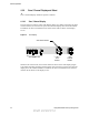
Table Of Contents
- Table of Contents
- Safety Information
- Radio Overview
- Controls & Display
- Dual Controls & External Speaker
- General Operation
- 4.1 Basic Operation
- 4.1.1 Turning Power ON and Setting Volume
- 4.1.2 Power-Up Password
- 4.1.3 Speaking into the Microphone
- 4.1.4 Display Backlight Control
- 4.1.5 Display Viewing Angle and Contrast Adjust
- 4.1.6 Zone / Channel Display and Select
- 4.1.7 Setting Squelch Control
- 4.1.8 Transmit Disable
- 4.1.9 Operation At Extended Range
- 4.1.10 Preventing Vehicle Battery Discharge
- 4.1.11 Cleaning the Control Head
- 4.1.12 Radio Service
- 4.2 Operating Modes
- 4.1 Basic Operation
- Radio Wide Features
- 5.1 Option Buttons
- 5.2 Menu Mode
- 5.3 Time-Out Timer
- 5.4 Home Channel Select
- 5.5 Power Output Select
- 5.6 Alert Tone Select
- 5.7 Power Turn-Off Delay
- 5.8 Horn Alert
- 5.9 Microphone Off-Hook Detect
- 5.10 Surveillance Mode
- 5.11 Public Address
- 5.12 Scanning
- 5.13 Scan Lists
- 5.14 Global Positioning System (GPS)
- 5.15 Over the Air Programming
- Conventional Features
- 6.1 Monitoring Before Transmitting
- 6.2 Monitor Mode
- 6.3 Busy Channel Lockout
- 6.4 Call Guard Squelch
- 6.5 Penalty Timer
- 6.6 Conversation Timer
- 6.7 Repeater Talk-Around
- 6.8 Displaying Transmit / Receive Frequency
- 6.9 Emergency Alarm and Call
- 6.10 Conventional Mode Channel Scanning
- 6.11 Standard Conventional Calls
- 6.12 DTMF / ANI Signaling
- 6.13 Project 25 Mode Features
- 6.13.1 Digital Unit ID
- 6.13.2 Talkgroup ID
- 6.13.3 Network Access Code (NAC)
- 6.13.4 EFJohnson System Out of Range Indicator
- 6.13.5 EFJohnson System Automatic Registration
- 6.13.6 P25 Group Calls
- 6.13.7 P25 Unit Calls
- 6.13.8 P25 Conventional Telephone Calls
- 6.13.9 Call Alert
- 6.13.10 Call History
- 6.13.11 Messaging
- 6.13.12 Status Messaging
- 6.13.13 P25 Packet Data
- 6.14 Keypad Programming
- 6.15 Text Messaging
- 6.16 Sending Global Positioning System (GPS) Data
- SMARTNET / SmartZone / P25 Trunked Features
- 7.1 Analog and Digital Operation
- 7.2 Viewing Unit ID
- 7.3 Standard Group Calls
- 7.4 Private (Unit-To-Unit) Calls
- 7.5 Telephone Calls
- 7.6 Call Alert
- 7.7 Messaging
- 7.8 Sending Status Conditions
- 7.9 Emergency Alarm and Call
- 7.10 Failsoft Operation
- 7.11 SMARTNET / SmartZone / P25 Trunked Scanning Features
- 7.12 Dynamic Regrouping
- 7.13 SmartZone and P25 Trunking Unique Features
- 7.13.1 Busy Override
- 7.13.2 Site Trunking
- 7.13.3 Determining Current Site and Searching for a New Site
- 7.13.4 Locking / Unlocking a Site
- 7.13.5 Auto Site Search
- 7.13.6 ZoneFail Site Lock
- 7.13.7 P25 Wide Area Scan
- 7.13.8 Normal P25 and SmartZone Control Channel Hunt
- 7.13.9 Talkgroup Steering through System Access Permissions
- 7.13.10 P25 Wide Area Scan
- 7.13.11 Radio Information
- Secure Communication (Encryption)
- 8.1 Encryption Algorithms
- 8.2 Encryption Keys
- 8.3 Clear / Secure Strapping
- 8.4 Security Settings Override
- 8.4.1 Conventional (P25) Talkgroup Security Override
- 8.4.2 Secure Call Behavior
- 8.4.2.1 Failsoft, Group Regroup or Dynamic Regroup Call
- 8.4.2.2 Channel with only a Talkgroup Specified
- 8.4.2.3 Channel with both a Talkgroup and Announcement Group Specified
- 8.4.2.4 Channel with only an Announcement Group Specified
- 8.4.2.5 Announcement Group Call
- 8.4.2.6 Emergency Calls on Emergency Groups
- 8.4.3 Scan Mode Behavior
- 8.5 Over-The-Air Rekeying (OTAR)
- 8.6 Radio Setup For Encryption
- 8.7 Radio OTAR Capabilities
- Data Features
- Tones & Error Messages
- Service Information

Viking VM600 Mobile Radio Operating Manual 3-5
Dual Control Configurations Section 3 - Dual Controls & External Speaker
3.1.6 Master / Slave Programming
In both dual control configurations, either control head can be designated as the Master
and the other as the Slave. The Master control head controls the volume of its internal
speaker and any external speakers that are connected to the radio's 8-pin accessory
connector (see installation manual for connection details).
All Viking VM600 mobile radios ship from the factory with the dash-mount control head
and any remote control heads set as Master, so in all dual-control configurations, one
control head must be set as the Slave to ensure correct operation.
Control head addressing is set as follows:
1 Power up the mobile radio
2 Press buttons F3, F4 and F5 at the same time, and release (see Figure 3.4).
3 The display will read "ADDRESS 21" if the control head is configured as the Master,
or "ADDRESS 22" thru "ADDRESS 27" if the control head is configured as the Slave.
4 Rotate the Select knob to select the appropriate address.
5 After a short time-out period, display will read "CYCLE PWR"
6 Power the radio off and back on, and the configuration will be updated.
Figure 3.4 Control Head Option Buttons
Programmable Option Buttons
F1 F2 F3 F4 F5 F6
Draft 4/29/2014