
User's Manual


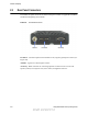


Table Of Contents
- Table of Contents
- Safety Information
- Radio Overview
- Controls & Display
- Dual Controls & External Speaker
- General Operation
- 4.1 Basic Operation
- 4.1.1 Turning Power ON and Setting Volume
- 4.1.2 Power-Up Password
- 4.1.3 Speaking into the Microphone
- 4.1.4 Display Backlight Control
- 4.1.5 Display Viewing Angle and Contrast Adjust
- 4.1.6 Zone / Channel Display and Select
- 4.1.7 Setting Squelch Control
- 4.1.8 Transmit Disable
- 4.1.9 Operation At Extended Range
- 4.1.10 Preventing Vehicle Battery Discharge
- 4.1.11 Cleaning the Control Head
- 4.1.12 Radio Service
- 4.2 Operating Modes
- 4.1 Basic Operation
- Radio Wide Features
- 5.1 Option Buttons
- 5.2 Menu Mode
- 5.3 Time-Out Timer
- 5.4 Home Channel Select
- 5.5 Power Output Select
- 5.6 Alert Tone Select
- 5.7 Power Turn-Off Delay
- 5.8 Horn Alert
- 5.9 Microphone Off-Hook Detect
- 5.10 Surveillance Mode
- 5.11 Public Address
- 5.12 Scanning
- 5.13 Scan Lists
- 5.14 Global Positioning System (GPS)
- 5.15 Over the Air Programming
- Conventional Features
- 6.1 Monitoring Before Transmitting
- 6.2 Monitor Mode
- 6.3 Busy Channel Lockout
- 6.4 Call Guard Squelch
- 6.5 Penalty Timer
- 6.6 Conversation Timer
- 6.7 Repeater Talk-Around
- 6.8 Displaying Transmit / Receive Frequency
- 6.9 Emergency Alarm and Call
- 6.10 Conventional Mode Channel Scanning
- 6.11 Standard Conventional Calls
- 6.12 DTMF / ANI Signaling
- 6.13 Project 25 Mode Features
- 6.13.1 Digital Unit ID
- 6.13.2 Talkgroup ID
- 6.13.3 Network Access Code (NAC)
- 6.13.4 EFJohnson System Out of Range Indicator
- 6.13.5 EFJohnson System Automatic Registration
- 6.13.6 P25 Group Calls
- 6.13.7 P25 Unit Calls
- 6.13.8 P25 Conventional Telephone Calls
- 6.13.9 Call Alert
- 6.13.10 Call History
- 6.13.11 Messaging
- 6.13.12 Status Messaging
- 6.13.13 P25 Packet Data
- 6.14 Keypad Programming
- 6.15 Text Messaging
- 6.16 Sending Global Positioning System (GPS) Data
- SMARTNET / SmartZone / P25 Trunked Features
- 7.1 Analog and Digital Operation
- 7.2 Viewing Unit ID
- 7.3 Standard Group Calls
- 7.4 Private (Unit-To-Unit) Calls
- 7.5 Telephone Calls
- 7.6 Call Alert
- 7.7 Messaging
- 7.8 Sending Status Conditions
- 7.9 Emergency Alarm and Call
- 7.10 Failsoft Operation
- 7.11 SMARTNET / SmartZone / P25 Trunked Scanning Features
- 7.12 Dynamic Regrouping
- 7.13 SmartZone and P25 Trunking Unique Features
- 7.13.1 Busy Override
- 7.13.2 Site Trunking
- 7.13.3 Determining Current Site and Searching for a New Site
- 7.13.4 Locking / Unlocking a Site
- 7.13.5 Auto Site Search
- 7.13.6 ZoneFail Site Lock
- 7.13.7 P25 Wide Area Scan
- 7.13.8 Normal P25 and SmartZone Control Channel Hunt
- 7.13.9 Talkgroup Steering through System Access Permissions
- 7.13.10 P25 Wide Area Scan
- 7.13.11 Radio Information
- Secure Communication (Encryption)
- 8.1 Encryption Algorithms
- 8.2 Encryption Keys
- 8.3 Clear / Secure Strapping
- 8.4 Security Settings Override
- 8.4.1 Conventional (P25) Talkgroup Security Override
- 8.4.2 Secure Call Behavior
- 8.4.2.1 Failsoft, Group Regroup or Dynamic Regroup Call
- 8.4.2.2 Channel with only a Talkgroup Specified
- 8.4.2.3 Channel with both a Talkgroup and Announcement Group Specified
- 8.4.2.4 Channel with only an Announcement Group Specified
- 8.4.2.5 Announcement Group Call
- 8.4.2.6 Emergency Calls on Emergency Groups
- 8.4.3 Scan Mode Behavior
- 8.5 Over-The-Air Rekeying (OTAR)
- 8.6 Radio Setup For Encryption
- 8.7 Radio OTAR Capabilities
- Data Features
- Tones & Error Messages
- Service Information

3-2 Viking VM600 Mobile Radio Operating Manual
Dual Control Configurations Section 3 - Dual Controls & External Speaker
Both dual control configurations can be configured and ordered as a complete kit. Existing
Viking mobiles can also be converted to dual control configurations by the purchase of
accessory kits, as described in the EFJohnson Subscriber Radio Accessories Catalog.
Contact your EFJohnson Sales Representative for additional information.
3.1.1 Remote Conversion Kit 250-5300-002
This kit provides the material required to convert an existing dash-mount mobile to a
remote-mount configuration. The kit includes:
- Blank faceplate for mobile unit
- Rear shroud for remote control head
- Remote control head mounting bracket
- Single remote accessory cable (part number 597-5357-706)
- 17 ft. remote control cable (part number 597-5357-775-02)
The kit does not include the control head removal tool (part number 721-5100-010) which
must be ordered separately if required.
The remote control cable is also available in 6 ft. (part number 597-5357-775-01) and 50
ft. (part number 597-5357-775-03) lengths, but these must be ordered separately.
3.1.2 Remote Control Head Kit 250-5300-003
This kit includes the material required to add a remote control head to an existing dash-
mount or remote-mount configuration. The kit includes:
- ES Remote control head with mounting bracket.
Due to differing operational requirements, the following items are not included in the kit
and must be ordered separately:
- Microphone - see section 3 for further details
- Remote control cable - order 6 ft., 17 ft. or 50 ft. cable as required
- Remote accessory cable - see section 2.3 for further details
Configurations using two remote control heads require the Dual Remote / Accessory /
Data / Siren cable (part number 597-5357-741).
Configurations using a dash-mount mobile with one remote control head can use the
following remote accessory cables, depending on the application:
- Single Remote / Accessory cable (part number 597-5357-706)
- Single Remote / Accessory / UDDI cable (part number 597-5357-736)
- Single Remote / Accessory / Data / Siren cable (part number 597-5357-716)
Draft 4/29/2014