
User's Manual


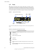
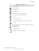


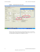
Table Of Contents
- Table of Contents
- Safety Information
- Radio Overview
- Controls & Display
- Dual Controls & External Speaker
- General Operation
- 4.1 Basic Operation
- 4.1.1 Turning Power ON and Setting Volume
- 4.1.2 Power-Up Password
- 4.1.3 Speaking into the Microphone
- 4.1.4 Display Backlight Control
- 4.1.5 Display Viewing Angle and Contrast Adjust
- 4.1.6 Zone / Channel Display and Select
- 4.1.7 Setting Squelch Control
- 4.1.8 Transmit Disable
- 4.1.9 Operation At Extended Range
- 4.1.10 Preventing Vehicle Battery Discharge
- 4.1.11 Cleaning the Control Head
- 4.1.12 Radio Service
- 4.2 Operating Modes
- 4.1 Basic Operation
- Radio Wide Features
- 5.1 Option Buttons
- 5.2 Menu Mode
- 5.3 Time-Out Timer
- 5.4 Home Channel Select
- 5.5 Power Output Select
- 5.6 Alert Tone Select
- 5.7 Power Turn-Off Delay
- 5.8 Horn Alert
- 5.9 Microphone Off-Hook Detect
- 5.10 Surveillance Mode
- 5.11 Public Address
- 5.12 Scanning
- 5.13 Scan Lists
- 5.14 Global Positioning System (GPS)
- 5.15 Over the Air Programming
- Conventional Features
- 6.1 Monitoring Before Transmitting
- 6.2 Monitor Mode
- 6.3 Busy Channel Lockout
- 6.4 Call Guard Squelch
- 6.5 Penalty Timer
- 6.6 Conversation Timer
- 6.7 Repeater Talk-Around
- 6.8 Displaying Transmit / Receive Frequency
- 6.9 Emergency Alarm and Call
- 6.10 Conventional Mode Channel Scanning
- 6.11 Standard Conventional Calls
- 6.12 DTMF / ANI Signaling
- 6.13 Project 25 Mode Features
- 6.13.1 Digital Unit ID
- 6.13.2 Talkgroup ID
- 6.13.3 Network Access Code (NAC)
- 6.13.4 EFJohnson System Out of Range Indicator
- 6.13.5 EFJohnson System Automatic Registration
- 6.13.6 P25 Group Calls
- 6.13.7 P25 Unit Calls
- 6.13.8 P25 Conventional Telephone Calls
- 6.13.9 Call Alert
- 6.13.10 Call History
- 6.13.11 Messaging
- 6.13.12 Status Messaging
- 6.13.13 P25 Packet Data
- 6.14 Keypad Programming
- 6.15 Text Messaging
- 6.16 Sending Global Positioning System (GPS) Data
- SMARTNET / SmartZone / P25 Trunked Features
- 7.1 Analog and Digital Operation
- 7.2 Viewing Unit ID
- 7.3 Standard Group Calls
- 7.4 Private (Unit-To-Unit) Calls
- 7.5 Telephone Calls
- 7.6 Call Alert
- 7.7 Messaging
- 7.8 Sending Status Conditions
- 7.9 Emergency Alarm and Call
- 7.10 Failsoft Operation
- 7.11 SMARTNET / SmartZone / P25 Trunked Scanning Features
- 7.12 Dynamic Regrouping
- 7.13 SmartZone and P25 Trunking Unique Features
- 7.13.1 Busy Override
- 7.13.2 Site Trunking
- 7.13.3 Determining Current Site and Searching for a New Site
- 7.13.4 Locking / Unlocking a Site
- 7.13.5 Auto Site Search
- 7.13.6 ZoneFail Site Lock
- 7.13.7 P25 Wide Area Scan
- 7.13.8 Normal P25 and SmartZone Control Channel Hunt
- 7.13.9 Talkgroup Steering through System Access Permissions
- 7.13.10 P25 Wide Area Scan
- 7.13.11 Radio Information
- Secure Communication (Encryption)
- 8.1 Encryption Algorithms
- 8.2 Encryption Keys
- 8.3 Clear / Secure Strapping
- 8.4 Security Settings Override
- 8.4.1 Conventional (P25) Talkgroup Security Override
- 8.4.2 Secure Call Behavior
- 8.4.2.1 Failsoft, Group Regroup or Dynamic Regroup Call
- 8.4.2.2 Channel with only a Talkgroup Specified
- 8.4.2.3 Channel with both a Talkgroup and Announcement Group Specified
- 8.4.2.4 Channel with only an Announcement Group Specified
- 8.4.2.5 Announcement Group Call
- 8.4.2.6 Emergency Calls on Emergency Groups
- 8.4.3 Scan Mode Behavior
- 8.5 Over-The-Air Rekeying (OTAR)
- 8.6 Radio Setup For Encryption
- 8.7 Radio OTAR Capabilities
- Data Features
- Tones & Error Messages
- Service Information

2-8 Viking VM600 Mobile Radio Operating Manual
Controls & Display
2.2.2 Display
The Lightning Control Head includes a highly readable display. The display is a mono-
chrome display with 320 x 80 pixels. The display supports both the Classic Single Line
display mode or enhanced Dual Line functionality. In Classic Single Line mode, display
will have primary fields corresponding to the fields available on the mobile Viking control
head, with the addition of the soft menu keys. Figure 2.7 shows the front panel display.
Figure 2.7 Lightning Control Head Display
Table 2.2 lists the symbols used on the display to indicate various operating modes and
status.
Table 2.2 Lightning Display Operating/Status Mode Symbols
Lightning Control Head Symbols
Keypad programming/edit mode. Displayed when the radio is in a mode where you can edit
radio settings.
Monitor mode enabled
Repeater Talk-Around mode enabled
Scan Enabled
Security Enabled
The current channel is in the enabled scan list (only when scan is on or when in scan edit
mode)
The current channel is the priority channel in the enabled scan list (only when scan is on or
when in scan edit mode)
Zone
Number
Channel
NumberOperating Mode Symbols / Status
One-Touch Button LabelsChannel
Name
Draft 4/29/2014