
User's Manual


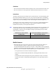


Table Of Contents
- Table of Contents
- Safety Information
- Radio Overview
- Controls & Display
- Dual Controls & External Speaker
- General Operation
- 4.1 Basic Operation
- 4.1.1 Turning Power ON and Setting Volume
- 4.1.2 Power-Up Password
- 4.1.3 Speaking into the Microphone
- 4.1.4 Display Backlight Control
- 4.1.5 Display Viewing Angle and Contrast Adjust
- 4.1.6 Zone / Channel Display and Select
- 4.1.7 Setting Squelch Control
- 4.1.8 Transmit Disable
- 4.1.9 Operation At Extended Range
- 4.1.10 Preventing Vehicle Battery Discharge
- 4.1.11 Cleaning the Control Head
- 4.1.12 Radio Service
- 4.2 Operating Modes
- 4.1 Basic Operation
- Radio Wide Features
- 5.1 Option Buttons
- 5.2 Menu Mode
- 5.3 Time-Out Timer
- 5.4 Home Channel Select
- 5.5 Power Output Select
- 5.6 Alert Tone Select
- 5.7 Power Turn-Off Delay
- 5.8 Horn Alert
- 5.9 Microphone Off-Hook Detect
- 5.10 Surveillance Mode
- 5.11 Public Address
- 5.12 Scanning
- 5.13 Scan Lists
- 5.14 Global Positioning System (GPS)
- 5.15 Over the Air Programming
- Conventional Features
- 6.1 Monitoring Before Transmitting
- 6.2 Monitor Mode
- 6.3 Busy Channel Lockout
- 6.4 Call Guard Squelch
- 6.5 Penalty Timer
- 6.6 Conversation Timer
- 6.7 Repeater Talk-Around
- 6.8 Displaying Transmit / Receive Frequency
- 6.9 Emergency Alarm and Call
- 6.10 Conventional Mode Channel Scanning
- 6.11 Standard Conventional Calls
- 6.12 DTMF / ANI Signaling
- 6.13 Project 25 Mode Features
- 6.13.1 Digital Unit ID
- 6.13.2 Talkgroup ID
- 6.13.3 Network Access Code (NAC)
- 6.13.4 EFJohnson System Out of Range Indicator
- 6.13.5 EFJohnson System Automatic Registration
- 6.13.6 P25 Group Calls
- 6.13.7 P25 Unit Calls
- 6.13.8 P25 Conventional Telephone Calls
- 6.13.9 Call Alert
- 6.13.10 Call History
- 6.13.11 Messaging
- 6.13.12 Status Messaging
- 6.13.13 P25 Packet Data
- 6.14 Keypad Programming
- 6.15 Text Messaging
- 6.16 Sending Global Positioning System (GPS) Data
- SMARTNET / SmartZone / P25 Trunked Features
- 7.1 Analog and Digital Operation
- 7.2 Viewing Unit ID
- 7.3 Standard Group Calls
- 7.4 Private (Unit-To-Unit) Calls
- 7.5 Telephone Calls
- 7.6 Call Alert
- 7.7 Messaging
- 7.8 Sending Status Conditions
- 7.9 Emergency Alarm and Call
- 7.10 Failsoft Operation
- 7.11 SMARTNET / SmartZone / P25 Trunked Scanning Features
- 7.12 Dynamic Regrouping
- 7.13 SmartZone and P25 Trunking Unique Features
- 7.13.1 Busy Override
- 7.13.2 Site Trunking
- 7.13.3 Determining Current Site and Searching for a New Site
- 7.13.4 Locking / Unlocking a Site
- 7.13.5 Auto Site Search
- 7.13.6 ZoneFail Site Lock
- 7.13.7 P25 Wide Area Scan
- 7.13.8 Normal P25 and SmartZone Control Channel Hunt
- 7.13.9 Talkgroup Steering through System Access Permissions
- 7.13.10 P25 Wide Area Scan
- 7.13.11 Radio Information
- Secure Communication (Encryption)
- 8.1 Encryption Algorithms
- 8.2 Encryption Keys
- 8.3 Clear / Secure Strapping
- 8.4 Security Settings Override
- 8.4.1 Conventional (P25) Talkgroup Security Override
- 8.4.2 Secure Call Behavior
- 8.4.2.1 Failsoft, Group Regroup or Dynamic Regroup Call
- 8.4.2.2 Channel with only a Talkgroup Specified
- 8.4.2.3 Channel with both a Talkgroup and Announcement Group Specified
- 8.4.2.4 Channel with only an Announcement Group Specified
- 8.4.2.5 Announcement Group Call
- 8.4.2.6 Emergency Calls on Emergency Groups
- 8.4.3 Scan Mode Behavior
- 8.5 Over-The-Air Rekeying (OTAR)
- 8.6 Radio Setup For Encryption
- 8.7 Radio OTAR Capabilities
- Data Features
- Tones & Error Messages
- Service Information

Viking VM600 Mobile Radio Operating Manual xv
Safety Information
Guidelines
• User awareness instructions should accompany device when transferred to other users.
• Do not use this device if the operational requirements described herein are not met.
Instructions
Transmit no more than the rated duty factor of 50% of the time. To transmit (talk), push
the Push-To-Talk (PTT) button. To receive calls, release the PTT button. Transmitting
50% of the time, or less, is important because this radio generates measurable RF energy
exposure only when transmitting (in terms of measuring for standards compliance).
Transmit only when people outside the vehicle are at least the recommended minimum
lateral distance away, as shown in Table 1, from a properly installed according to
installation instructions, externally-mounted antenna.
Note The following table lists the recommended minimum lateral distance for bystanders in an
uncontrolled environment from transmitting types of antennas (i.e., monopoles over a
ground plane, or dipoles) at several different ranges of rated radio power for mobile
radios installed in a vehicle.
Mobile Antennas
• Install antennas at the center of the roof or the center of the trunk deck taking into
account the bystander exposure conditions of backseat passengers and the
recommended minimum lateral distances in Table 1. These mobile antenna installation
guidelines are limited to metal body motor vehicles or vehicles with appropriate ground
planes. The antenna installation should additionally be in accordance with:
- The requirements of the antenna manufacturer/supplier.
- Instructions in the Radio Installation Manual, including minimum antenna cable
lengths.
- The installation manual should provide specific information of how to install the
antennas to facilitate recommended operating distances to all potentially exposed
persons.
Rated Power of Vehicle-Installed
Two-Way Radio
Recommended Minimum Lateral Distance
From Transmitting Antenna
Up to 50 watts 1.0 meter
50-110 watts 1.5 meter
Draft 4/29/2014