User's Manual
Table Of Contents
- 0020600045_Viking VP600 Portable Radio Operating Manual
- Features
- Controls and Display
- General Operation
- Radio-wide Features
- 4.1 Viewing Radio Information
- 4.2 Option Keys / Buttons
- 4.3 Feature Enable / Disable
- 4.4 Menu Mode
- 4.5 Function Recall
- 4.6 Time-Out Timer
- 4.7 Home Channel Select
- 4.8 Power Output Select
- 4.9 Alert Tone Select
- 4.10 Surveillance Mode
- 4.11 Scanning
- 4.12 Global Positioning System (GPS)
- 4.13 Radio Service
- 4.14 RSSI
- 4.15 Fire Ground Mode
- Conventional Mode Features
- 5.1 Monitoring Before Transmitting
- 5.2 Monitor Mode
- 5.3 Busy Channel Lockout
- 5.4 Call Guard Squelch
- 5.5 Penalty Timer
- 5.6 Conversation Timer
- 5.7 Repeater Talkaround
- 5.8 Displaying Transmit / Receive Frequency
- 5.9 Emergency Alarm and Call
- 5.10 Conventional Mode Scanning
- 5.11 Standard Conventional Calls
- 5.12 ANI Signaling Options
- 5.13 Project 25 Mode Features
- 5.13.1 Digital Unit ID
- 5.13.2 Talkgroup ID
- 5.13.3 Network Access Code
- 5.13.4 Out of Range (EFJohnson Conventional) Indication
- 5.13.5 Automatic (EFJohnson Conventional) Registration
- 5.13.6 P25 Group Calls
- 5.13.7 Talkgroup Scan
- 5.13.8 P25 Unit Calls
- 5.13.9 P25 Conventional Telephone Calls
- 5.13.10 Call Alert
- 5.13.11 Call History
- 5.13.12 Messaging
- 5.13.13 Status Messaging
- 5.13.14 P25 Packet Data
- 5.14 Keypad Programming
- 5.15 Text Messaging
- 5.16 Fire Ground Mode
- SmartNet / SmartZone / P25 Trunked Features
- 6.1 Analog and Digital Operation
- 6.2 Standard Group Calls
- 6.3 Unit Calls
- 6.4 Telephone Calls
- 6.5 Call Alert
- 6.6 Messaging
- 6.7 Sending Status Conditions
- 6.8 Emergency Alarm and Call
- 6.9 Failsoft Operation
- 6.10 SmartNet / SmartZone / P25 Trunked Scanning Features
- 6.11 Dynamic Regrouping
- 6.12 SmartZone and P25 Trunking Unique Features
- 6.13 Zone Password
- Messages
- Secure Communication (Encryption)
- Data Features
- Service Information
- 00FCC Safety Requirements

3-10 Viking™ VP600 Portable Radio Operating Manual
General Operation
Note The Li-P battery can only be charged in an approved battery charger. Charging lithium
batteries in nickel only chargers can result in overcharging the batteries and can damage
the cells through swelling.
Do not transmit in close proximity to the charger base (see following).
Do not expose the charger base to high level RF signals while a battery is being charged
because this may cause a charger fuse to blow (especially in the UHF range). Radios
programmed for SmartNet/SmartZone operation, for example, may affiliate while in the
charger which causes them to automatically key. Therefore, do not leave radio power on
while charging as described above.
3.4.4 Belt clip Installation
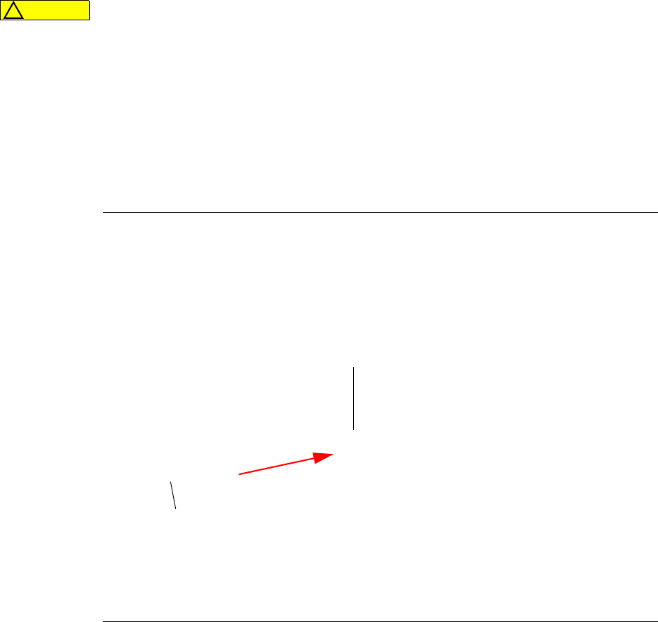
Remove the battery and slide the belt clip into the slot on the battery until it locks into
place (see Figure 3.2). To remove the belt clip, squeeze the tab on the end of the belt clip
and slide the belt clip out.
Figure 3.2 Belt clip Installation
3.4.5 Connecting an Accessory
To connect an accessory to the transceiver, proceed as follows:
1 Remove the protective cover over the accessory jack on the side of the transceiver.
2 Insert the hook on the lower end of the accessory connector into the slot on the side of
the transceiver.
3 Rotate the latch open, press the connector against the transceiver, and then release the
latch to lock the connector in place.
CAUTION
!
Belt Clip
Slot for clip
Battery Pack
Retention Spring Tab


