
Operating Manual Part 15

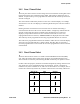

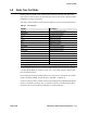
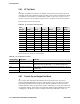
Table Of Contents
- Safety Information
- General
- Controls And Display
- General Operation
- Radio Wide Features
- Conventional Features
- 5.1 Monitoring Before Transmitting
- 5.2 Monitor Mode
- 5.3 Busy Channel Lockout
- 5.4 Call Guard Squelch
- 5.5 Penalty Timer
- 5.6 Conversation Timer
- 5.7 Repeater Talk-Around
- 5.8 Displaying Transmit / Receive Frequency
- 5.9 Emergency Alarm and Call
- 5.10 Conventional Mode Scanning
- 5.11 Standard Conventional Calls
- 5.12 DTMF / ANI Signaling
- 5.13 Project 25 Mode Features
- 5.14 Keypad Programming
- 5.15 Text Messaging
- 5.16 Sending Global Positioning System (GPS) Data
- SMARTNET / SmartZone / P25 Trunked Features
- 6.1 Analog and Digital Operation
- 6.2 Viewing Unit ID
- 6.3 Standard Group Calls
- 6.4 Private (Unit-To-Unit) Calls
- 6.5 Telephone Calls
- 6.6 Call Alert
- 6.7 Messaging
- 6.8 Sending Status Conditions
- 6.9 Emergency Alarm and Call
- 6.10 Failsoft Operation
- 6.11 SMARTNET / SmartZone / P25 Trunked Scanning Features
- 6.12 Dynamic Regrouping
- 6.13 SmartZone and P25 Trunking Unique Features
- 6.13.1 Busy Override
- 6.13.2 Site Trunking
- 6.13.3 Determining Current Site and Searching for a New Site
- 6.13.4 Locking / Unlocking a Site
- 6.13.5 Auto Site Search
- 6.13.6 ZoneFail Site Lock
- 6.13.7 P25 Wide Area Scan
- 6.13.8 Normal P25 and SmartZone Control Channel Hunt
- 6.13.9 Talkgroup Steering through System Access Permissions
- 6.13.10 P25 Wide Area Scan
- 6.14 P25 Trunking Unique Features
- Miscellaneous
- Determining Available Options
- Password Description
- Secure Communication (Encryption)
- Service Information

3-12 5300 ES Series Mobile Radio Operating Manual October 2008
General Operation
3.8.1 RF Test Mode
In the RF Test Mode, the radio has a set number of frequencies and tests that can be run
depending on the radio’s band. The frequencies that can be tested are summarized in Table
3.2 and the test environments are summarized in Table 3.3. The user can press <F2> to
advance to the next test environment and press <F3> to advance to the next test channel.
Refer to Table 2 for the test channels.
Refer to Table 3.3 for the test environments.
3.8.2 Control Top and Keypad Test Mode
Once Control Top and Keypad Test Mode is selected from the menu, all icons are
displayed and the LED lights red. Upon release of the F1 button, the radio is in Control
Top and Keypad Mode. In this mode, all of the buttons and knobs on the radio can be
tested to determine if they are operating correctly. Performing any event emits a tone and
an appropriate display. If the radio is in Control Top and Keypad Test Mode but no action
is taking place, the display continues to display the message “CH TEST”. Table 3.4
Table 3.2 RF Test Mode Frequencies (MHz)
Test
Channel
VHF Rx VHF Tx UHF Rx UHF Tx
700/800
MHz Rx
700/800
MHz Tx
136.075 136.025 380.075 380.025 764.0625 764.0125
142.075 142.125 390.075 390.025 769.0625 769.0125
154.275 154.225 400.075 400.025 775.9375 775.9875
160.175 160.125 411.075 411.025 851.0625 794.0125
168.125 168.075 424.975 424.925 860.0625 809.0125
173.925 173.975 425.075 425.025 869.9375 823.9875
435.075 435.025 851.0625 851.0125
445.075 445.025 860.0625 860.0125
457.075 457.025 869.9375 869.8875
10 469.975 469.925
Table 3.3 RF Test Mode Environments
Display String Description Function
ANA Carrier Squelch Normal radio operation: Rx – unsquelch if carrier detected Tx – mic audio.
CTCSS Tone Private-Line CTCSS operation: Rx – unsquelch if carrier and 192.8 Hz tone detected,
always show carrier with green LED. Tx – mic audio plus 192.8 Hz tone.
DIG P25 Digital Conventional Tone operation: (equivalent to high deviation test in PCTune) Rx – none Tx
– 1200 Hz tone.
MON Carrier Unsquelch Monitor operation: Rx – always unsquelch Tx – mic audio.